The vector stencil library "HVAC controls" contains contains 24 HVAC control symbols: sensors, actuators, timers, controllers, I/ O points.
Use it for drawing HVAC system diagrams, heating, ventilation, air conditioning, refrigeration, automated building control, and environmental control design floor
plans and equipment layouts.
"HVAC (... Heating, Ventilation and Air Conditioning) is a control system that applies regulation to a heating and/ or air conditioning system. ...
Central controllers and most terminal unit controllers are programmable, meaning the direct digital control program code may be customized for the intended use. The program features include time schedules, setpoints, controllers, logic, timers, trend logs, and alarms. The unit controllers typically have analog and digital inputs that allow measurement of the variable (temperature, humidity, or pressure) and analog and digital outputs for control of the transport medium (hot/ cold water and/ or steam). Digital inputs are typically (dry) contacts from a control device, and analog inputs are typically a voltage or current measurement from a variable (temperature, humidity, velocity, or pressure) sensing device. Digital outputs are typically relay contacts used to start and stop equipment, and analog outputs are typically voltage or current signals to control the movement of the medium (air/ water/ steam) control devices such as valves, dampers, and motors." [HVAC control system. Wikipedia]
The vector stencils example "Design elements - HVAC controls" is included in HVAC Plans solution from the Building Plans area of ConceptDraw Solution
Park.
HVAC control symbols

Electrical Symbols — Analog and Digital Logic

Electrical Symbols, Electrical Diagram Symbols

Electrical Drawing Software and Electrical Symbols

How To use House Electrical Plan Software


Electrical Symbols — Transmission Paths
Electrical Symbols — Delay Elements

Electrical Symbols — Resistors

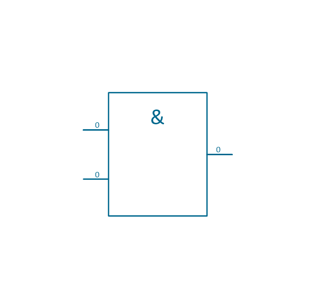
The vector stencils library "Analog and digital logic" contains 40 element symbols of logic (threshold) gates, bistable current switches, current controllers, regulators, electrical generators, and amplifiers.
Use it for drawing the digital and analog functions in electronic circuit diagrams and electrical schematics in the ConceptDraw PRO diagramming and vector drawing software extended with the Electrical Engineering solution from the Engineering area of ConceptDraw Solution Park.
www.conceptdraw.com/ solution-park/ engineering-electrical
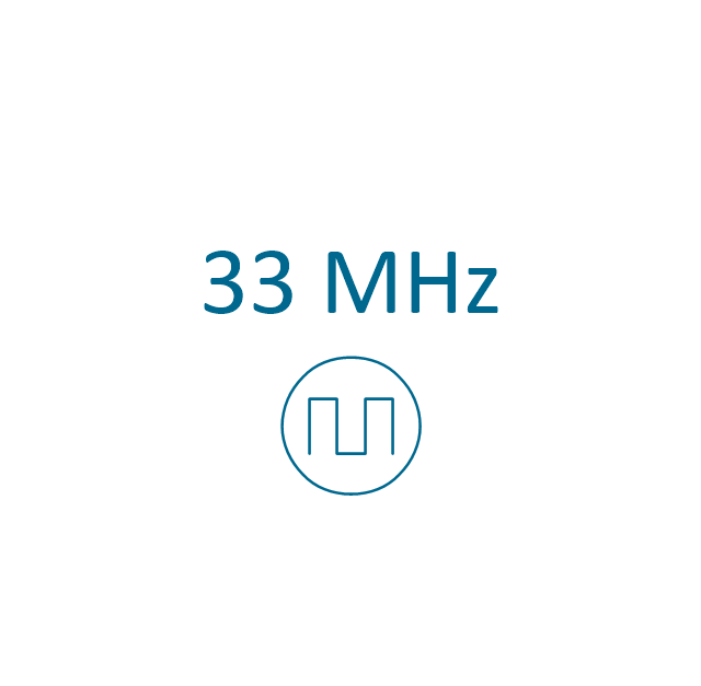
Clock
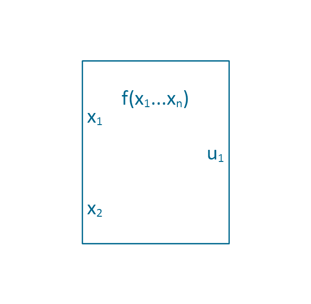
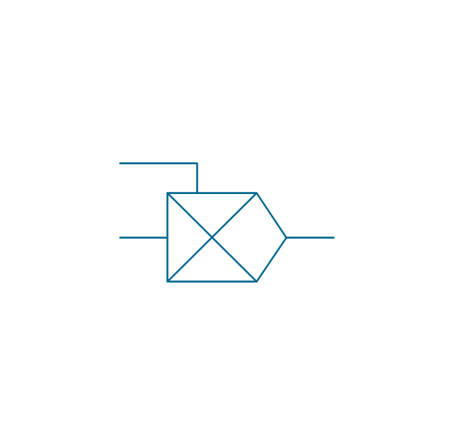
Function generator
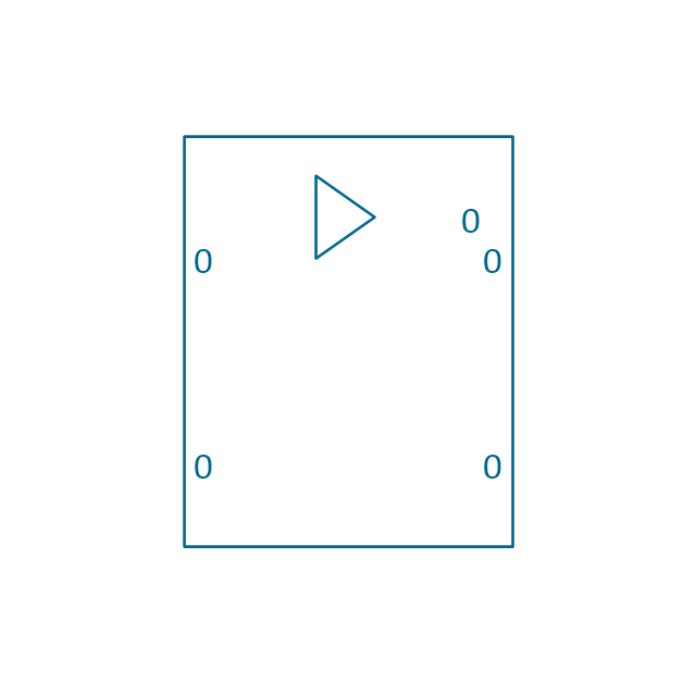
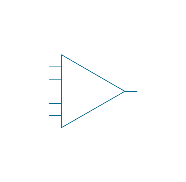
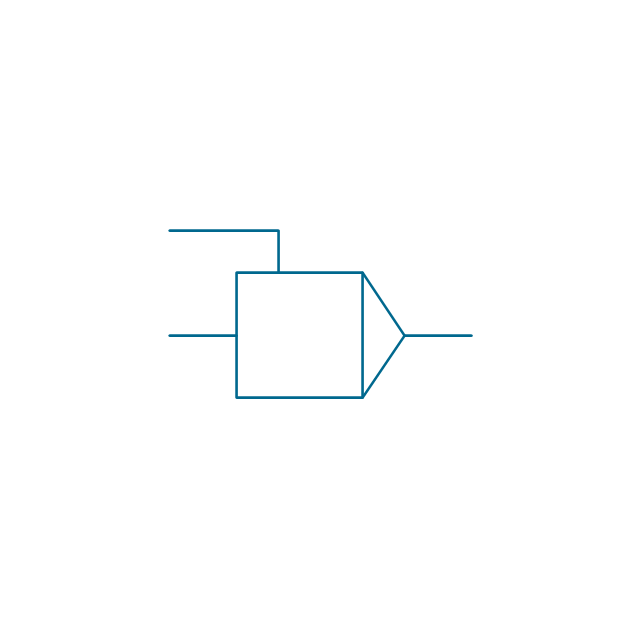
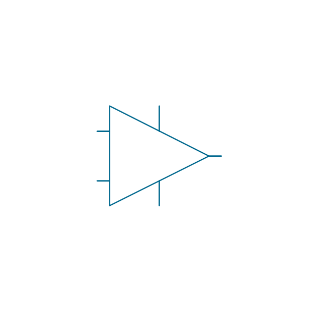
Amplifier
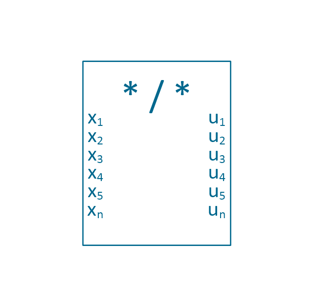
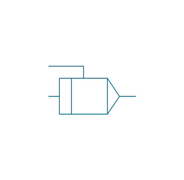
Converter
Logic gates
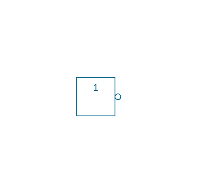
Inverter

Inverter 2
Buffer

Buffer 2

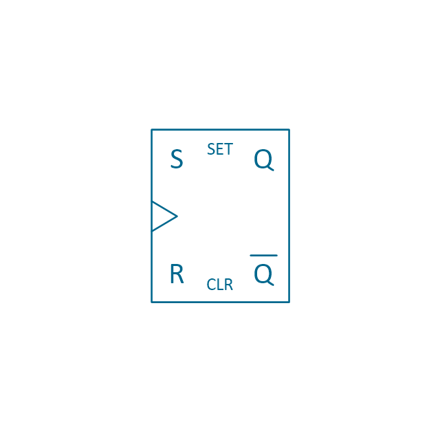
RS Flip-flop
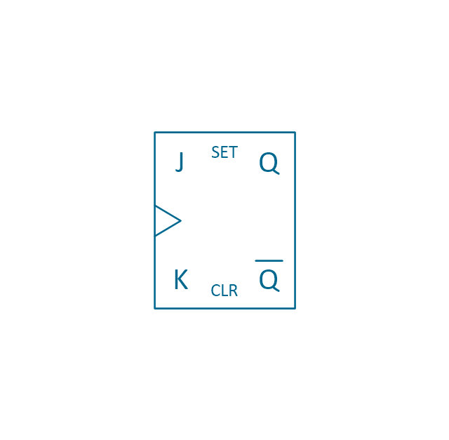
JK Flip-flop
Latch Flip-flop
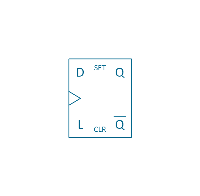
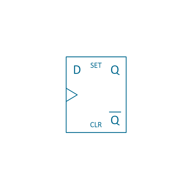
D Flip-flop
Analog symbol

Digital symbol

Negative logic dot

Potentiometer
Potentiometer 2
Positional servo
Piezoelectric crystal, 4 electrodes

Piezoelectric crystal, 3 electrodes

Piezoelectric crystal, 2 electrodes

I/O port bidirectional
I/O port unidirectional
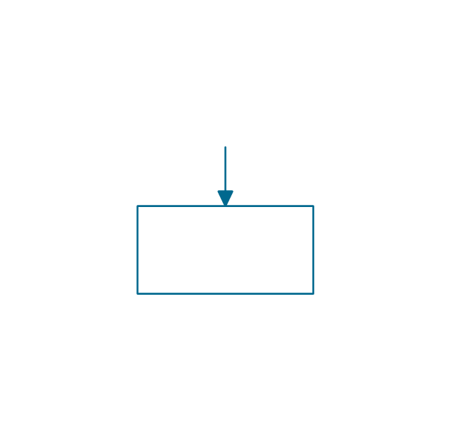
Square signal

Sine wave signal
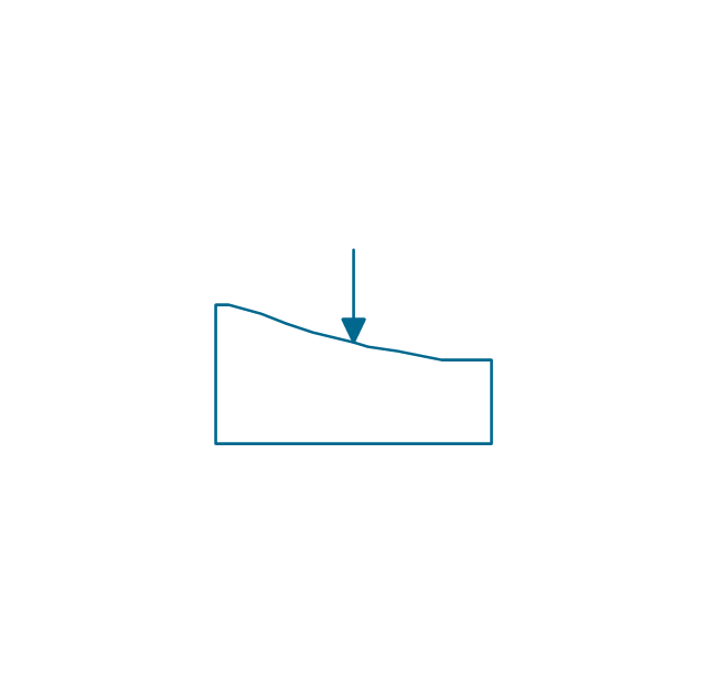
Sawtooth signal

Ramp signal
3 state data signal

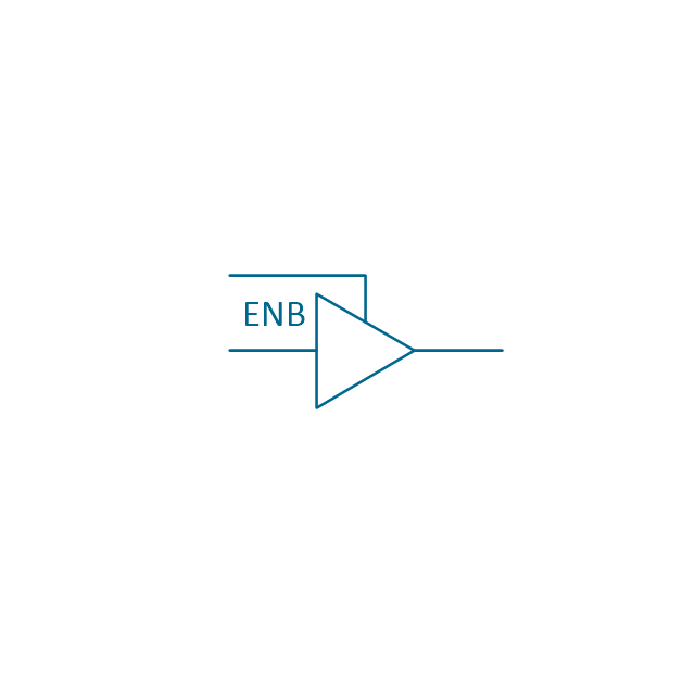
Three-state buffer
Integrator
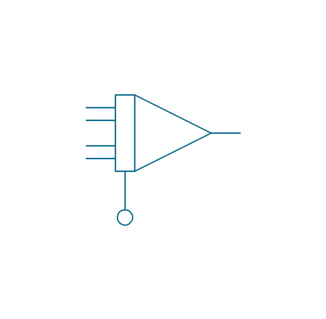
Summing amplifier
Multiplier
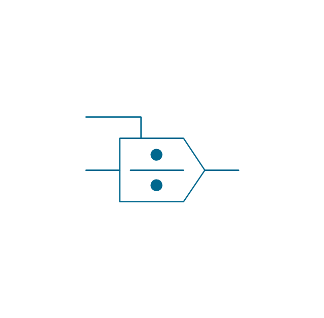
Divider
Function generator 2
Generalized integrator
Operational amplifier

Operational amplifier 2
Switch point
Switch point 2
Electrical Symbols — Switches and Relays

- HVAC controls - Vector stencils library | Design elements - HVAC ...
- Design elements - Alarm and access control | Electrical Symbols ...
- Control Symbols And Units
- Design elements - HVAC controls | Electrical Symbols — Switches ...
- How to Create a HVAC Plan | Design elements - HVAC controls ...
- Mechanical Drawing Symbols | Design elements - HVAC controls ...
- Design elements - HVAC controls | Design elements - Valves ...
- Floor Plan Smoke Detector Symbol
- Symbol Digital
- Design elements - HVAC controls | Design elements - Switches ...