The vector stenvils library "Outlets" contains 57 symbols of electrical outlets for drawing building interior design, electrical floor plans and layouts of AC power plugs and sockets.
"AC power plugs and sockets are devices that allow electrically operated equipment to be connected to the primary alternating current (AC) power supply in a building. Electrical plugs and sockets differ in voltage and current rating, shape, size and type of connectors. The types used in each country are set by national standards, some of which are listed in the IEC technical report TR 60083, Plugs and socket-outlets for domestic and similar general use standardized in member countries of IEC.
Plugs and sockets for portable appliances started becoming available in the 1880s, to replace connections to light sockets with easier to use wall-mounted outlets. A proliferation of types developed to address the issues of convenience and protection from electric shock. Today there are approximately 20 types in common use around the world, and many obsolete socket types are still found in older buildings. Co-ordination of technical standards has allowed some types of plugs to be used over wide regions to facilitate trade in electrical appliances, and for the convenience of travellers and consumers of imported electrical goods. Some multi-standard sockets allow use of several different types of plugs; improvised or unapproved adapters between incompatible sockets and plugs may not provide the full safety and performance of an approved adapter." [AC power plugs and sockets. Wikipedia]
The example "Design elements - Outlets" was created using the ConceptDraw PRO diagramming and vector drawing software extended with the Electric and Telecom Plans solution from the Building plans area of ConceptDraw Solution Park.
Electrical outlet symbols

Electrical Symbols, Electrical Diagram Symbols

How To use House Electrical Plan Software


Swim Lane Flowchart Symbols

 Network Layout Floor Plans
Network Layout Floor Plans solution extends ConceptDraw DIAGRAM software functionality with powerful tools for quick and efficient documentation the network equipment and displaying its location on the professionally designed Network Layout Floor Plans. Never before creation of Network Layout Floor Plans, Network Communication Plans, Network Topologies Plans and Network Topology Maps was not so easy, convenient and fast as with predesigned templates, samples, examples and comprehensive set of vector design elements included to the Network Layout Floor Plans solution. All listed types of plans will be a good support for the future correct cabling and installation of network equipment.
Example of DFD for Online Store (Data Flow Diagram)


Entity Relationship Diagram Software for Mac

Critical Path Method in ConceptDraw PROJECT
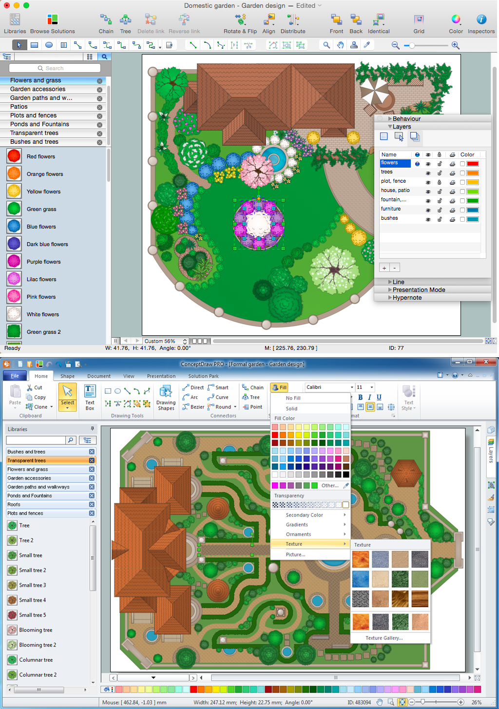
Landscape Architecture with ConceptDraw DIAGRAM
PROBLEM ANALYSIS. Identify and Structure Factors


- Design elements - Outlets | Cafe electrical floor plan | Types Of ...
- Duplex Triplex Single Convenience Outlet
- Symbol For Different Types Of Light In Electrical Layout
- Symbol For Convenience Outlet
- Electrical Receptacle Symbols
- Design elements - Outlets | Power socket outlet layout | Design ...
- Design elements - Outlets | Design elements - Electrical and telecom ...
- Types Of Convenience Outlets
- Design elements - Outlets | Building Drawing Design Element ...
- Design elements - Outlets | Outlets - Vector stenvils library | Power ...