Design Element: Rack Diagram for Network Diagrams
.png "Network Diagramming Tools, Design Elements - Rack Diagram (Win Mac)")

The Data Flow Diagrams solution from the Software Development area of ConceptDraw Solution Park provides three vector stencils libraries for drawing DFD using the ConceptDraw PRO diagramming and vector drawing software . The design elements library "Data flow diagram (DFD)" contains 15 symbols for drawing both context-level data flow diagram and Level 1 DFD. The design elements library "DFD, Gane-Sarson notation contains 12 symbols of Gane-Sarson DFD notation. The design elements library "DFD, Yourdon and Coad notation contains 22 symbols of Yourdon/ DeMarco DFD notation.
Use these DFD symbol libraries to design the process-oriented models, data-oriented models, data flowcharts, data process diagrams, structured analysis diagrams, and information flow diagrams.
"A data flow diagram (DFD) is a graphical representation of the "flow" of data through an information system, modeling its process aspects. Often they are a preliminary step used to create an overview of the system which can later be elaborated. DFDs can also be used for the visualization of data processing (structured design).
A DFD shows what kinds of information will be input to and output from the system, where the data will come from and go to, and where the data will be stored. It does not show information about the timing of processes, or information about whether processes will operate in sequence or in parallel (which is shown on a flowchart)." [Data flow diagram. Wikipedia]
The example "Design elements - Data Flow Diagram (DFD)" is included in the Data Flow Diagrams solution.
DFD symbols
.png--diagram-flowchart-example.png)
Design Element: IVR for Network Diagrams
")
Network Diagramming Software for Design Computer and Network Diagrams
_Win_Mac.png "Network Diagramming Software, Design Elements — Computer and Network (Windows, Macintosh)")
The vector stencils library "IDEF0 diagrams" contains 18 symbols for drawing IDEF0 function modeling diagrams using the ConceptDraw PRO diagramming and vector drawing software.
"The IDEF0 model ... is based on a simple syntax. Each activity is described by a verb-based label placed in a box. Inputs are shown as arrows entering the left side of the activity box while output are shown as exiting arrows on the right side of the box. Controls are displayed as arrows entering the top of the box and mechanisms are displayed as arrows entering from the bottom of the box. Inputs, Controls, Outputs, and Mechanisms are all referred to as concepts.
- Arrow : A directed line, composed of one or more arrow segments, that models an open channel or conduit conveying data or objects from source (no arrowhead) to use (with arrowhead). There are 4 arrow classes: Input Arrow, Output Arrow, Control Arrow, and Mechanism Arrow (includes Call Arrow). See Arrow Segment, Boundary Arrow, Internal Arrow.
- Box : A rectangle, containing a name and number, used to represent a function.
- Context : The immediate environment in which a function (or set of functions on a diagram) operates.
- Decomposition : The partitioning of a modeled function into its component functions.
- Fork : The junction at which an IDEF0 arrow segment (going from source to use) divides into two or more arrow segments. May denote unbundling of meaning.
- Function : An activity, process, or transformation (modeled by an IDEF0 box) identified by a verb or verb phrase that describes what must be accomplished.
- Join : The junction at which an IDEF0 arrow segment (going from source to use) merges with one or more other arrow segments to form a single arrow segment. May denote bundling of arrow segment meanings.
- Node : A box from which child boxes originate; a parent box. See Node Index, Node Tree, Node Number, Node Reference, Diagram Node Number." [IDEF0. Wikipedia]
The example "Design elements - IDEF0 diagram" is included in the IDEF0 Diagrams solution from the Software Development area of ConceptDraw Solution Park.
IDEF0 symbols

Design Element: Active Directory for Network Diagrams
")
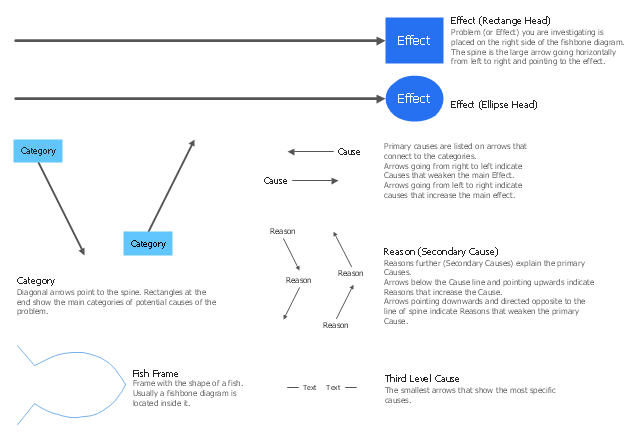
The library of vector stencils "Fishbone diagrams" contains 13 symbols for drawing the Ishikawa diagrams using the ConceptDraw PRO diagramming and vector drawing software.
"Ishikawa diagrams were popularized by Kaoru Ishikawa in the 1960s, who pioneered quality management processes in the Kawasaki shipyards, and in the process became one of the founding fathers of modern management.
The basic concept was first used in the 1920s, and is considered one of the seven basic tools of quality control. It is known as a fishbone diagram because of its shape, similar to the side view of a fish skeleton." [Ishikawa diagram. Wikipedia]
"The Seven Basic Tools of Quality is a designation given to a fixed set of graphical techniques identified as being most helpful in troubleshooting issues related to quality. They are called basic because they are suitable for people with little formal training in statistics and because they can be used to solve the vast majority of quality-related issues.
The seven tools are:
(1) Cause-and-effect diagram (also known as the "fishbone" or Ishikawa diagram);
(2) Check sheet;
(3) Control chart;
(4) Histogram;
(5) Pareto chart;
(6) Scatter diagram;
(7) Stratification (alternately, flow chart or run chart)." [Seven Basic Tools of Quality. Wikipedia]
The example "Design elements - Fishbone diagram" is included in the Fishbone Diagrams solution from the Management area of ConceptDraw Solution Park.
Ishikawa diagram symbols
- Design elements - Data Flow Diagram (DFD)
- DFD Library - Design elements | DFD Library System | Data Flow ...
- Data Flow Diagrams | Data Flow Diagram (DFD) | Design elements ...
- Flow Chart Symbols | Design elements - Data Flow Diagram (DFD ...
- ERD Symbols and Meanings | Design Element : Chen for Entity ...
- Design Element : Rack Diagram for Network Diagrams | Rack ...
- ERD Symbols and Meanings | Entity Relationship Diagram Symbols ...
- Target and Circular Diagrams | Design elements - Target and ...
- Network Diagramming Software for Design Cisco Network Diagrams ...
- UML Deployment Diagram | Design Element : Basic Network for ...
- DFD Library System | Data Flow Diagrams | DFD Library - Design ...
- Cisco Network Design | ConceptDraw PRO Network Diagram Tool ...
- Best Vector Drawing Application for Mac OS X | Design Element ...
- Entity Relationship Diagram Software for Design Crows Foot ER ...
- Aerospace and Transport | Aerospace - Design Elements | Fishbone ...
- UML Activity Diagram , Design Elements | UML Use Case Diagram ...
- Cisco Multimedia, Voice, Phone. Cisco icons, shapes, stencils and ...
- ERD Symbols and Meanings | Entity-Relationship Diagram (ERD ...
- Wireless Network Elements | Network Diagramming Software for ...
- Design elements - Computer network