Design Element: Rack Diagram for Network Diagrams
.png "Network Diagramming Tools, Design Elements - Rack Diagram (Win Mac)")

Design Element: Active Directory for Network Diagrams
")
Design Element: Basic Network for Network Diagrams
.png "Network Diagramming Tools, Design Elements - Basic Network (Win Mac)")
Network Diagramming Software for Network Active Directory Diagrams
")
Design Element: IVR for Network Diagrams
")
Network Diagramming Software for Design Basic Network Diagrams
_Win_Mac.png "Network Diagramming Software, Design Elements - Basic Network (Windows, Macintosh)")
Network Diagramming Software for Design Computer and Network Diagrams
_Win_Mac.png "Network Diagramming Software, Design Elements — Computer and Network (Windows, Macintosh)")
The vector stencils library "Cisco network topology" contains 89 symbols of Cisco network devices and design elements for drawing computer network topology diagrams using the ConceptDraw PRO diagramming and vector drawing software.
"Network topology is an arrangement of the various elements (links, nodes, etc.) of a computer network. Essentially, it is the topological structure of a network, and may be depicted physically or logically. Physical topology refers to the placement of the network's various components, including device location and cable installation, while logical topology shows how data flows within a network, regardless of its physical design. Distances between nodes, physical interconnections, transmission rates, and/ or signal types may differ between two networks, yet their topologies may be identical.
A good example is a local area network (LAN): Any given node in the LAN has one or more physical links to other devices in the network; graphically mapping these links results in a geometric shape that can be used to describe the physical topology of the network. Conversely, mapping the data flow between the components determines the logical topology of the network." [Network topology. Wikipedia]
The example "Design elements - Cisco network topology" is included in the Cisco Network Diagrams solution from the Computer and Networks area of ConceptDraw Solution Park.
Cisco network topology symbols

The vector stencils library "Network layout floorplan" contain 34 symbol icons for drawing computer network floor plans and communication equipment and cabling layouts.
"Networking hardware may also be known as network equipment or computer networking devices. Units which are the last receiver or generate data are called hosts or data terminal equipment.
All these terms refer to devices facilitating the use of a computer network. Specifically, they mediate data in a computer network. ...
Typically, networking hardware includes gateways, routers, network bridges, switches, hubs, and repeaters. But it also includes hybrid network devices such as multilayer switches, protocol converters, bridge routers, proxy servers, firewalls, network address translators, multiplexers, network interface controllers, wireless network interface controllers, modems, ISDN terminal adapters, line drivers, wireless access points, networking cables and other related hardware.
The most common kind of networking hardware today is a copper-based Ethernet adapter because of its standard inclusion on most modern computer systems. Wireless networking has, however, become increasingly popular, especially for portable and handheld devices.
Other hardware prevalent in computer networking includes data center equipment (such as file servers, database servers and storage areas), network services (such as DNS, DHCP, email, etc.) as well as devices which assure content delivery." [Networking hardware. Wikipedia]
The shapes example "Design elements - Network layout floorplan" was created using the ConceptDraw PRO diagramming and vector drawing software extended with the Network Layout Floor Plans solution from the Computer and Networks area of ConceptDraw Solution Park.
Network layout floor plan symbols

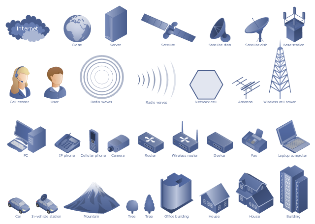
"A telecommunications network is a collection of terminal nodes, links and any intermediate nodes which are connected so as to enable telecommunication between the terminals. The transmission links connect the nodes together. The nodes use circuit switching, message switching or packet switching to pass the signal through the correct links and nodes to reach the correct destination terminal. Each terminal in the network usually has a unique address so messages or connections can be routed to the correct recipients. The collection of addresses in the network is called the address space. Examples of telecommunications networks are: computer networks, Internet, telephone network, global Telex network, aeronautical ACARS network." [Telecommunications network. Wikipedia]
The example "Design elements - Telecommunication networks" was created using the ConceptDraw PRO diagramming and vector drawing software extended with the Telecommunication Network Diagrams solution from the Computer and Networks area of ConceptDraw Solution Park.
The example "Design elements - Telecommunication networks" was created using the ConceptDraw PRO diagramming and vector drawing software extended with the Telecommunication Network Diagrams solution from the Computer and Networks area of ConceptDraw Solution Park.
Telecom diagram symbols
The vector stencils library "Logical network diagram" contains 16 icon symbols.
Use these shapes for drawing logical computer network topology diagrams using the ConceptDraw PRO diagramming and vector drawing software.
The clipart example "Design elements - Logical network diagram" is included in the Computer and Networks solution from the Computer and Networks area of ConceptDraw Solution Park.
Logical network topology symbols

- Telecommunication Network Diagrams | Design elements ...
- Design elements - Electrical circuits | Electrical Engineering ...
- Design Element : Basic Network for Network Diagrams | Design ...
- Wide area network (WAN) topology. Computer and Network ...
- Network Diagram Examples | Design Element : Basic Network for ...
- Design Element : Rack Diagram for Network Diagrams | Rack ...
- Network Layout Floor Plans | Network Layout | Design elements ...
- Design Element : Computer and Network for Network Diagrams ...
- Process Flowchart | Design Element : IVR for Network Diagrams ...
- Rack Diagrams | Design Element : Rack Diagram for Network ...
- Design Element : Active Directory for Network Diagrams | Cisco ...
- Design Element : Rack Diagram for Network Diagrams | Building ...
- Computer and Networks Area | Computer Network Diagrams ...
- Design Element : Basic Network for Network Diagrams | Network ...
- Network Diagramming Software for Design Network Layout Diagrams
- Network Diagramming Software for Network Active Directory Diagrams
- Design Element : Computer and Network for Network Diagrams
- Design Elements - Alvarion, Cisco | Using Remote Networking ...
- Interactive Voice Response Network Diagram | Design Element : IVR ...