This site uses cookies. By continuing to browse the ConceptDraw site you are agreeing to our Use of Site Cookies.

Cloud Computing Architecture Diagrams

For documenting the Cloud Computing Architecture with a goal to facilitate the communication between stakeholders are successfully used the Cloud Computing Architecture diagrams. It is convenient and easy to draw various Cloud Computing Architecture diagrams in ConceptDraw DIAGRAM software with help of tools of the Cloud Computing Diagrams Solution from the Computer and Networks Area of ConceptDraw Solution Park.

Cloud Computing Architecture

The Cloud Computing Architecture is the structure of the system, which is based on the needs of end-user and includes the set of components and subcomponents required for cloud computing, among them cloud resources, services, middleware, software components, front-end platforms (cloud clients), cloud-based back end platforms (servers, storage), and a network (Internet, Intranet, Intercloud). When designing the Cloud Computing Architecture diagrams, the ConceptDraw DIAGRAM diagramming and vector drawing software advises to turn attention for the powerful Cloud Computing Diagrams solution from the extensive Computers and Network area of ConceptDraw Solution Park.

Information Architecture

You want design the Information Architecture and need a powerful software for this? ConceptDraw DIAGRAM extended with Enterprise Architecture Diagrams Solution from the Management Area is exactly what you need.

Computer Network Architecture. Computer and Network Examples

The network architecture and design specialization will help you gain the technical leadership skills you need to design and implement high-quality networks that support business needs.

Point to Point Network Topology

This sample was created in ConceptDraw DIAGRAM diagramming and vector drawing software using the Computer and Networks solution from Computer and Networks area of ConceptDraw Solution Park.
This sample shows the Point-to-point network topology.
Network topology is the topological structure of the computer network.
Point-to-point network topology is a simple topology that displays the network of exactly two hosts (computers, servers, switches or routers) connected with a cable. Point-to-point topology is widely used in the computer networking and computer architecture.

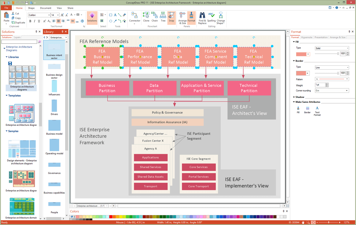
Garrett IA Diagrams with ConceptDraw DIAGRAM

Garrett IA diagrams are used at development of Internet-resources, in particulars at projecting of interactions of web-resource elements. The diagram of information architecture of the web resource which is constructed correctly with necessary details presents to developers the resource in comprehensible and visual way.
The vector stencils library "Azure architecture - Enterprise" contains 98 Microsoft Azure architecture symbols.
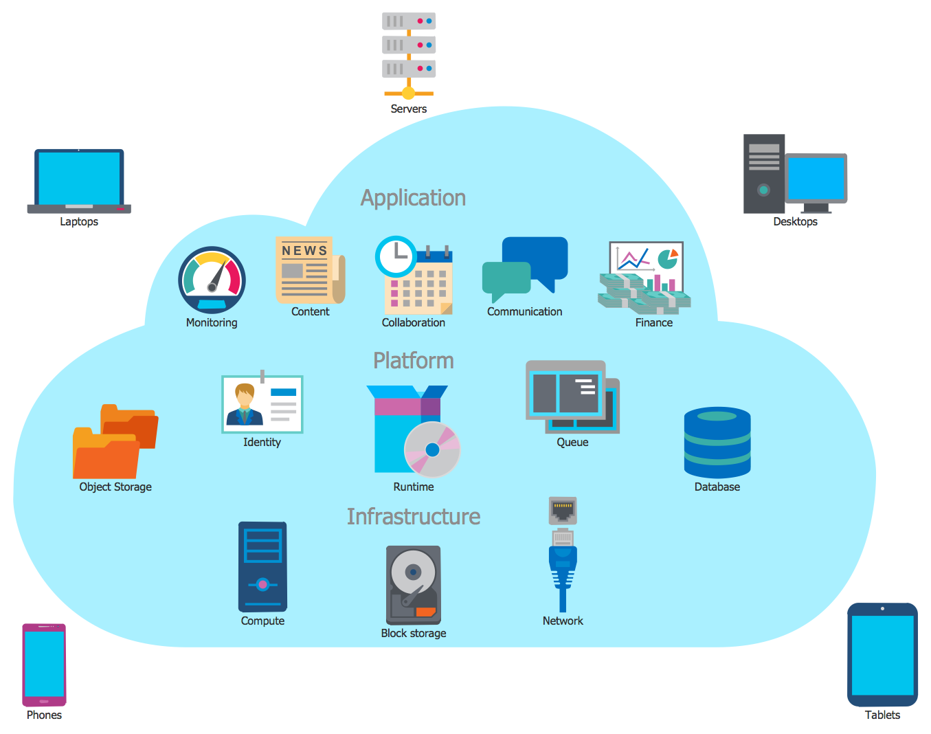
Use this enterprise cloud icon set to design your cloud computing architecture diagrams.
"Enterprise cloud computing is the special case of utilizing cloud computing for competitive advantage through breakout opportunities both for cost savings and, more importantly, for business innovation in terms of unprecedented speed and agility with vastly improved collaboration among business partners and customers." [whatis.techtarget.com/ definition/ Enterprise-Cloud-Computing-FAQ]
The symbols example "Design elements - Azure architecture - Enterprise" is included in the Azure Architecture solution from the Computer and Networks area of ConceptDraw Solution Park.
Enterprise cloud icon set
Enterprise cloud icon set, workstation client, wireless connection, website generic, web server, web, virtual machine, video, user permissions, user enterprise, unhealthy, tunnel, triggers, tool, tablet, table, stored procedures, storage, startup task, smartcard, shared folder, settings, server, generic, server, blade, server rack, server farm, server directory, secure virtual machine, script file, router, queue, protocol stack, plug and play, phone, performance monitor, performance, not allowed, network card, mouse, monitor running apps, monitor, message, management console, maintenance, lock, protected, lock unlocked, accessible, load testing, load balancer, generic, laptop computer, keyboard, key, permissions, internet, import generic, iPhone, healthy, health monitoring, generic code, gateway, folder, firewall, filter, file, event, enterprise, building, domain controller, document, directory federation services proxy, direct Access, feature, device, database synchronization, database server, database generic, connectors, code file, cluster server, cloud, client application, certificate, backup, online, backup, local, application, blank, application server, app generic, XML web service, Windows server, USB, UDF function, RPD remoting file, RMS connector, Powerpoint, PowerShell script file, Outlook, Azure pack, Android phone, AD FS,

Basic Flowchart Symbols and Meaning

Flowchart Symbols and Meaning - Provides a visual representation of basic flowchart symbols and their proposed use in professional workflow diagram, standard process flow diagram and communicating the structure of a well-developed web site, as well as their correlation in developing on-line instructional projects. See flowchart's symbols by specifics of process flow diagram symbols and workflow diagram symbols.
How to Build a Flowchart

Local area network (LAN). Computer and Network Examples

A local area network (LAN) is a devices network that connect with each other in the scope of a home, school, laboratory, or office. Usually, a LAN comprise computers and peripheral devices linked to a local domain server. All network appliances can use a shared printers or disk storage. A local area network serve for many hundreds of users. Typically, LAN includes many wires and cables that demand a previously designed network diagram. They are used by IT professionals to visually document the LANs physical structure and arrangement.
ConceptDraw - Perfect Network Diagramming Software with examples of LAN Diagrams. ConceptDraw Network Diagram is ideal for network engineers and network designers who need to draw Local Area Network diagrams.
How to Draw a Computer Network

Personal area (PAN) networks. Computer and Network Examples

A Personal area network (PAN) is a computer network that is used for data transmission between different personal devices (computers, telephones, digital devices, etc.) and for connecting to the higher level network and Internet. PANs can be wired with computer buses (USB and FireWire). A wireless personal area network (WPAN) can be made using the network technologies such as Bluetooth, IrDa, UWB, Z-Wave, ZigBee, Body Area Network. A personal area network handles the interconnection of IT devices at the surrounding of a single user. Generally, PAN contains from following such appliances: cordless mice and keyboards, cordless phone, Bluetooth handsets.
This example was created in ConceptDraw DIAGRAM using the Computer and Networks Area of ConceptDraw Solution Park and shows the Personal area network.