Piping and Instrumentation Diagram Software

The vector clipart library "Arrows" contains 37 arrows which you can easy use in your presentation slides and illustrations.
The clip art example "Arrows - Vector clipart library" was created in the ConceptDraw PRO diagramming and vector drawing software using the Presentation Clipart solution from the Illustration area of ConceptDraw Solution Park.
The clip art example "Arrows - Vector clipart library" was created in the ConceptDraw PRO diagramming and vector drawing software using the Presentation Clipart solution from the Illustration area of ConceptDraw Solution Park.
Moving up

Vertical moving

Moving down

Interaction arrows

Wavy arrow
Circular motion

Goal achievement

Moving ahead

Opposite direction

Motive forces

Arrow backward
Arrow forward
Arrow left
Arrow right
Arrow 1
Arrow 2
Arrow 3
Horizontal double arrow
Connecting arrow
Arched down

Arched up

Circular

Leftward

Rightward

Leftward blue

Rightward blue

Arrow backward round
Arrow forward round
Arrow round
Arrow left rounded square
Arrow right rounded square
Arrow 2 rounded square
Arrow 3 rounded square
Arrow forward square
Arrow backward square
Arrow left (white background)
Arrow right (white background)
The vector stencils library "Logical symbols" contains 49 logical symbols for drawing logical network topology diagrams.
"Logical topology, or signal topology, is the arrangement of devices on a computer network and how they communicate with one another. How devices are connected to the network through the actual cables that transmit data, or the physical structure of the network, is called the physical topology. Physical topology defines how the systems are physically connected. It represents the physical layout of the devices on the network. The logical topology defines how the systems communicate across the physical topologies.
Logical topologies are bound to network protocols and describe how data is moved across the network. ... EXAMPLE : twisted pair Ethernet is a logical bus topology in a physical star topology layout. While IBM's token ring is a logical ring topology, it is physically set up in star topology." [Logical topology. Wikipedia]
The icons example "Logical symbols - Vector stencils library" was created using the ConceptDraw PRO diagramming and vector drawing software extended with the Computer and Networks solution from the Computer and Networks area of ConceptDraw Solution Park.
www.conceptdraw.com/ solution-park/ computer-and-networks
Coaxial Line Tag

Fiber Optic Line Tag

Twisted Pair Line Tag

SC2200 Signaling Controller

Bridge

Network Management Appliance

Access Server (Communications Server)
-logical-symbols---vector-stencils-library.png--diagram-flowchart-example.png)
Terminal Server

Web Browser

Security Management, Cisco

Lock and Key

Lock

Key

Relational Database

Host

CSU/DSU

WAN

University

Government building

Home Office

Telecommuter House PC

Medium Building, Regular

Headquarters, Subdued

House, Regular

Small Business

Network Connector

Dynamic Connector

Line Connector

Line-curve Connector

Bus

FDDI Ring

Peer-to-peer

Token-ring

Star

Comm-link

Curved Bus

Ethernet

Cloud

Speaker

Microphone

Router

ATM Router

ISDN Switch

ATM Switch

ATM/FastGB Etherswitch

Workgroup Switch

Small Hub

100BaseT Hub

CDDI-FDDI

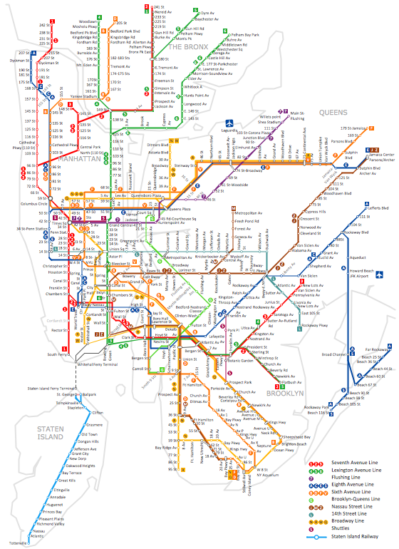
How to draw Metro Map style infographics? (New York)
 Floor Plans
Construction, repair and remodeling of the home, flat, office, or any other building or premise begins with the development of detailed building plan and floor plans. Correct and quick visualization of the building ideas is important for further construction of any building.
Building Drawing. Design Element: Piping Plan


Basic Flowchart Symbols and Meaning


The vector stencils library "Logical symbols" contains 49 logical symbols for drawing logical network topology diagrams.
"Logical topology, or signal topology, is the arrangement of devices on a computer network and how they communicate with one another. How devices are connected to the network through the actual cables that transmit data, or the physical structure of the network, is called the physical topology. Physical topology defines how the systems are physically connected. It represents the physical layout of the devices on the network. The logical topology defines how the systems communicate across the physical topologies.
Logical topologies are bound to network protocols and describe how data is moved across the network. ... EXAMPLE : twisted pair Ethernet is a logical bus topology in a physical star topology layout. While IBM's token ring is a logical ring topology, it is physically set up in star topology." [Logical topology. Wikipedia]
The icons example "Logical symbols - Vector stencils library" was created using the ConceptDraw PRO diagramming and vector drawing software extended with the Computer and Networks solution from the Computer and Networks area of ConceptDraw Solution Park.
www.conceptdraw.com/ solution-park/ computer-and-networks
"Logical topology, or signal topology, is the arrangement of devices on a computer network and how they communicate with one another. How devices are connected to the network through the actual cables that transmit data, or the physical structure of the network, is called the physical topology. Physical topology defines how the systems are physically connected. It represents the physical layout of the devices on the network. The logical topology defines how the systems communicate across the physical topologies.
Logical topologies are bound to network protocols and describe how data is moved across the network. ... EXAMPLE : twisted pair Ethernet is a logical bus topology in a physical star topology layout. While IBM's token ring is a logical ring topology, it is physically set up in star topology." [Logical topology. Wikipedia]
The icons example "Logical symbols - Vector stencils library" was created using the ConceptDraw PRO diagramming and vector drawing software extended with the Computer and Networks solution from the Computer and Networks area of ConceptDraw Solution Park.
www.conceptdraw.com/ solution-park/ computer-and-networks
Coaxial Line Tag
Fiber Optic Line Tag
Twisted Pair Line Tag
SC2200 Signaling Controller
Bridge
Network Management Appliance
Access Server (Communications Server)
Terminal Server
Web Browser
Security Management, Cisco
Lock and Key
Lock
Key
Relational Database
Host
CSU/DSU
WAN
University
Government building
Home Office
Telecommuter House PC
Medium Building, Regular
Headquarters, Subdued
House, Regular
Small Business
Network Connector
Dynamic Connector
Line Connector
Line-curve Connector
Bus
FDDI Ring
Peer-to-peer
Token-ring
Star
Comm-link
Curved Bus
Ethernet
Cloud
Speaker
Microphone
Router
ATM Router
ISDN Switch
ATM Switch
ATM/FastGB Etherswitch
Workgroup Switch
Small Hub
100BaseT Hub
CDDI-FDDI
The vector stencils library "Walls, shell and structure" contains 29 shapes of walls, windows, doors, pillars. Use it for drawing architectural blueprints, home and building design, space plans, and construction and house framing diagrams in the ConceptDraw PRO diagramming and vector drawing software extended with the Floor Plans solution from the Building Plans area of ConceptDraw Solution Park.
Wall
Wall 2
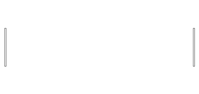
Exterior Wall

Curved Wall 1
Curved Wall 2
Curved Wall 3
Wall with pocket
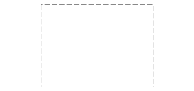
Room
L-Room

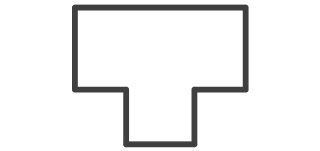
T-Room
Room Divider

Opening
Closet
Slab
Pilaster

Corner pilaster

Rectangular column, concrete
Rectangular column, steel
Rectangular column, wood
Circular column, concrete
Circular column, steel
Grid Origin

Grid Line

Window wall, inside edge
Window wall, middle
Window wall, outside edge
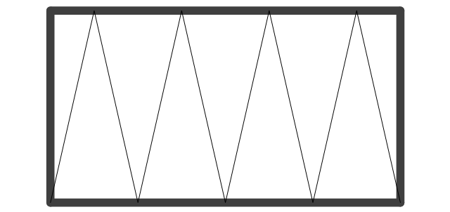
Curtain wall, inside edge
Curtain wall, middle
Curtain wall, outside edge
- Curved Line With Two Sides Arrow
- ConceptDraw Arrows10 Technology | How to Set Line Jumps for ...
- Arrows - Vector clipart library | Design elements - Arrows ...
- Downward Curved Arrow Clip Art
- Curved Arrow Double Png
- Double Sided Curved Arrow Clip Art
- Curved Arrow Circle Clip Art
- How to Connect Objects on PC | How to Set Line Jumps for Smart ...
- Sales arrows - Vector stencils library | HR arrows - Vector stencils ...
- Design elements - Arrows | Illustration | Arrows - Vector clipart library ...