Total Quality Management Definition

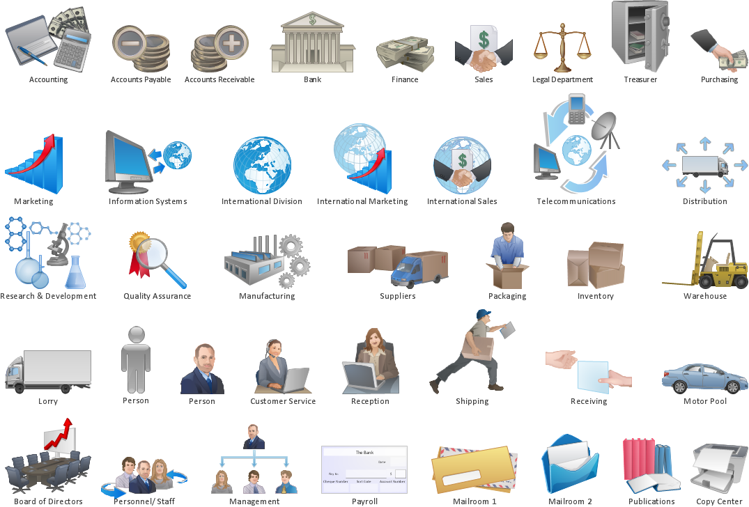
 Total Quality Management TQM Diagrams
Total Quality Management Diagrams solution extends ConceptDraw DIAGRAM software with samples, templates and vector stencils library for drawing the TQM flowcharts.
 Entity-Relationship Diagram (ERD)
Entity-Relationship Diagram (ERD) solution extends ConceptDraw DIAGRAM software with templates, samples and libraries of vector stencils from drawing the ER-diagrams by Chen's and crow’s foot notations.
 Entity-Relationship Diagram (ERD)
An Entity-Relationship Diagram (ERD) is a visual presentation of entities and relationships. That type of diagrams is often used in the semi-structured or unstructured data in databases and information systems. At first glance ERD is similar to a flowch
SIPOC Diagram

Diagramming Software for Design UML Use Case Diagrams


Structured Systems Analysis and Design Method (SSADM) with ConceptDraw DIAGRAM

Workflow Diagram Symbols
Business Processes

Quality Engineering Diagrams
Swim Lane Diagrams

Context Diagram Template

This template shows the Context Diagram. It was created in ConceptDraw DIAGRAM diagramming and vector drawing software using the Block Diagrams Solution from the “Diagrams” area of ConceptDraw Solution Park. The context diagram graphically identifies the system. external factors, and relations between them. It’s a high level view of the system. The context diagrams are widely used in software engineering and systems engineering for designing the systems that process the information.
 Fishbone Diagram
Fishbone Diagrams solution extends ConceptDraw DIAGRAM software with templates, samples and library of vector stencils for drawing the Ishikawa diagrams for cause and effect analysis.
 Seven Basic Tools of Quality
Manage quality control in the workplace, using fishbone diagrams, flowcharts, Pareto charts and histograms, provided by the Seven Basic Tools of Quality solution.
- Management Tools — Total Quality Management | Probability ...
- Fishbone Diagram | Total Quality Management with ConceptDraw
- Total Quality Management TQM Diagrams | Entity - Relationship
- Use Case Diagram For Library Management System Visio
- Seven Management and Planning Tools | Total Quality Management ...
- Probability Quality Control Tools | Management Tools — Total ...
- Management Tools — Total Quality Management | Probability ...
- Total Quality Management Value | Quality Mind Map | Probability ...
- Basic Flowchart Symbols and Meaning | ERD Symbols and ...
- Organizational Structure Total Quality Management | Total Quality ...
- Basic Flowchart Symbols and Meaning | Process Flowchart | ERD ...
- DFD Library System | Quality Management System | Fishbone ...
- Sequence Diagram For Library Management System Ppt
- Object Diagram For Library Management System Ppt
- Total Quality Management TQM Diagrams | TQM Software — Build ...
- Seven Management and Planning Tools | Process Flowchart | Total ...
- Total Quality Management TQM Diagrams
- TQM Diagram Example | TQM Software — Build Professional TQM ...
- Total Quality Management TQM Diagrams
- TQM diagrams - Vector stencils library | TQM diagram - Template ...