Diagramming Software for Design UML Communication Diagrams


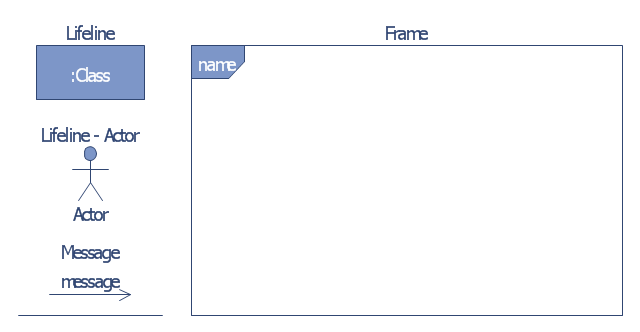
The vector stencils library "Bank UML communication diagram" contains 4 shapes for drawing UML communication (collaboration) diagrams.
Use it for object-oriented modeling of your bank information system.
"A communication diagram in the Unified Modeling Language (UML) 2.0, is a simplified version of the UML 1.x collaboration diagram.
A Communication diagram models the interactions between objects or parts in terms of sequenced messages. Communication diagrams represent a combination of information taken from Class, Sequence, and Use Case Diagrams describing both the static structure and dynamic behavior of a system.
However, communication diagrams use the free-form arrangement of objects and links as used in Object diagrams. In order to maintain the ordering of messages in such a free-form diagram, messages are labeled with a chronological number and placed near the link the message is sent over. Reading a communication diagram involves starting at message 1.0, and following the messages from object to object." [Communication diagram. Wikipedia]
This example of UML communication diagram symbols for the ConceptDraw PRO diagramming and vector drawing software is included in the ATM UML Diagrams solution from the Software Development area of ConceptDraw Solution Park.
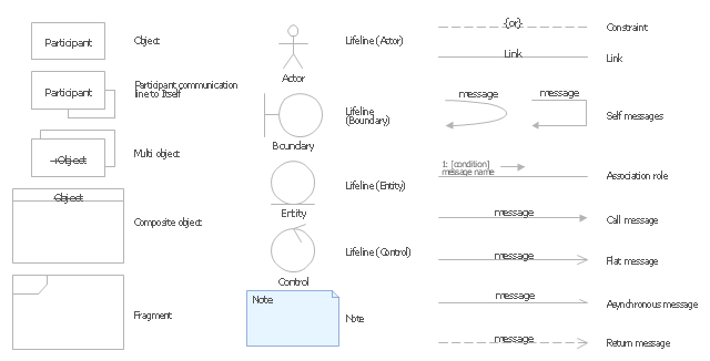
UML communication diagram symbols
The vector stencils library "UML communication diagrams" contains 23 symbols for the ConceptDraw PRO diagramming and vector drawing software.
"... communication diagrams use the free-form arrangement of objects and links as used in Object diagrams. In order to maintain the ordering of messages in such a free-form diagram, messages are labeled with a chronological number and placed near the link the message is sent over. Reading a communication diagram involves starting at message 1.0, and following the messages from object to object." [Communication diagram. Wikipedia]
The example "Design elements - UML communication diagrams" is included in the Rapid UML solution from the Software Development area of ConceptDraw Solution Park.
UML communication diagram symbols
UML Deployment Diagram. Design Elements

UML Component Diagram. Design Elements
")
UML Block Diagram

UML Collaboration Diagram. Design Elements

Design Elements for UML Diagrams

Process Flowchart


Basic Flowchart Symbols and Meaning


Network Diagramming Software for Design Rack Diagrams
_Win_Mac.png "Network Diagramming Software, Design Elements — Network Layout (Windows, Macintosh)")

Network Diagramming Software for Design Network Layout Diagrams
_Win_Mac.png "Network Diagramming Software, Design Elements - Network Layout (Windows, Macintosh)")
Design Element: Network Layout for Network Diagrams
.png "Network Diagramming Tools, Design Elements - Network Layout (Win Mac)")
Diagramming Software for Design UML Collaboration Diagrams

- Uml Communication Diagram
- Design elements - Bank UML communication diagram | Design ...
- Example Of Diagram In Communication Elements
- Telecommunication Network Diagrams | Design elements ...
- Diagramming Software for Design UML Communication Diagrams ...
- Design elements - UML communication diagrams | UML ...
- Design elements - Bank UML communication diagram
- Design elements - UML communication diagrams
- Design elements - Bank UML communication diagram | Computer ...
- Mobile satellite communication network diagram | Design elements ...
- UML Diagram | Flowchart Definition | Design elements - UML ...
- UML Deployment Diagram . Design Elements | Communication ...
- UML Deployment Diagram . Design Elements | Communication ...
- Mobile satellite TV network diagram | Communication medium ...
- Design elements - Transmission paths | Diagram Of Physical ...
- Unified communications diagram | Design elements - Interactive ...
- Unified communications diagram | Telecommunication networks ...
- Example Of A Diagram For Elements Of Communication
- Communication Diagram UML2.0 / Collaboration UML1.x | UML ...
- Diagramming Software for Design UML Communication Diagrams ...