Fishbone Diagram Procedure

How Do Fishbone Diagrams Solve Manufacturing Problems

 Fishbone Diagrams
The Fishbone Diagrams solution extends ConceptDraw DIAGRAM software with the ability to easily draw the Fishbone Diagrams (Ishikawa Diagrams) to clearly see the cause and effect analysis and also problem solving. The vector graphic diagrams produced using this solution can be used in whitepapers, presentations, datasheets, posters, and published technical material.
When To Use a Fishbone Diagram

Use a Fishbone Diagram to Attack Complex Problems
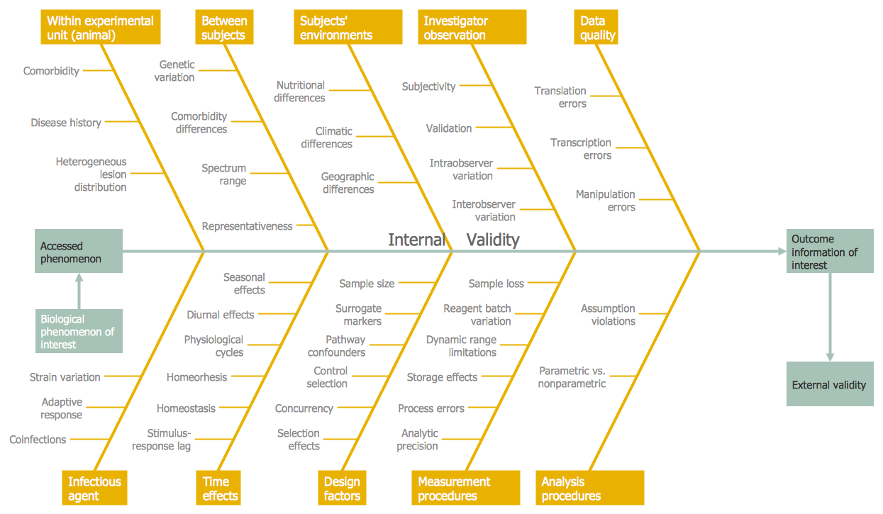
Fishbone Diagram Example

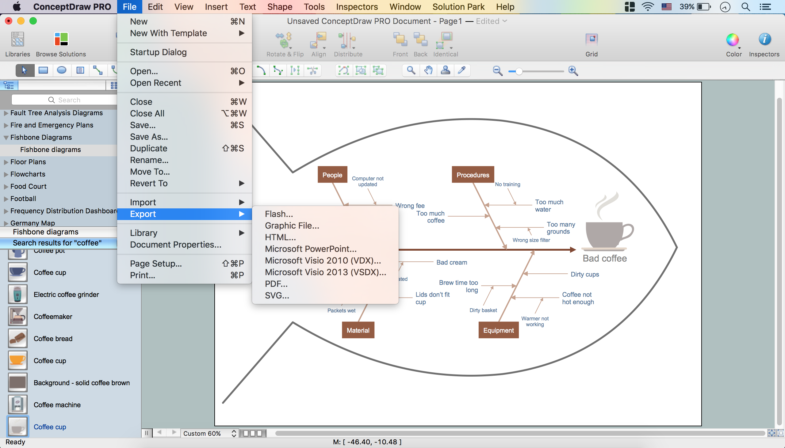
How to Construct a Fishbone Diagram
HelpDesk
How To Create Cause and Effect (Fishbone) Diagram in MS Visio
 Diagram in MS Visio")
 Chemical and Process Engineering
This chemical engineering solution extends ConceptDraw DIAGRAM.9.5 (or later) with process flow diagram symbols, samples, process diagrams templates and libraries of design elements for creating process and instrumentation diagrams, block flow diagrams (BFD
 Chemistry
This solution extends ConceptDraw DIAGRAM software with samples, template and libraries of vector stencils for drawing the Chemistry Illustrations for science and education.
- Fishbone Diagrams | Chemical and Process Engineering ...
- Chemistry | Website Wireframe | Gambar Fishbone
- Chemistry | Website Wireframe | Gambar Fish Bone
- Biology | Fishbone Diagrams | Divided Bar Diagrams | Attractive ...
- Biology | Fishbone Analysis In Biochemustry
- Fishbone Diagrams | Biology | Fishbone Science Example
- Computer Network Diagrams | Fishbone Diagrams | Chemistry All ...
- Types of Flowcharts | Electrical Symbols — Resistors | Fishbone ...
- Fishbone Diagram Example | Fishbone Diagrams | How to Add a ...
- Fishbone Diagrams | Target and Circular Diagrams | Workflow ...