Process Flow Diagram Symbols

 Chemical and Process Engineering
This chemical engineering solution extends ConceptDraw DIAGRAM.9.5 (or later) with process flow diagram symbols, samples, process diagrams templates and libraries of design elements for creating process and instrumentation diagrams, block flow diagrams (BFD
Flow Diagram Software

Chemical Engineering

Best Vector Drawing Application for Mac OS X

Process Flowchart


HelpDesk
How to Draw a Chemical Process Flow Diagram

Technical Drawing Software

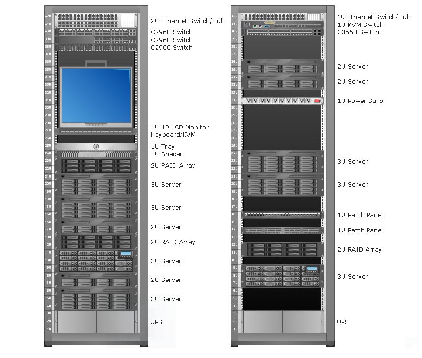
Rack Diagrams

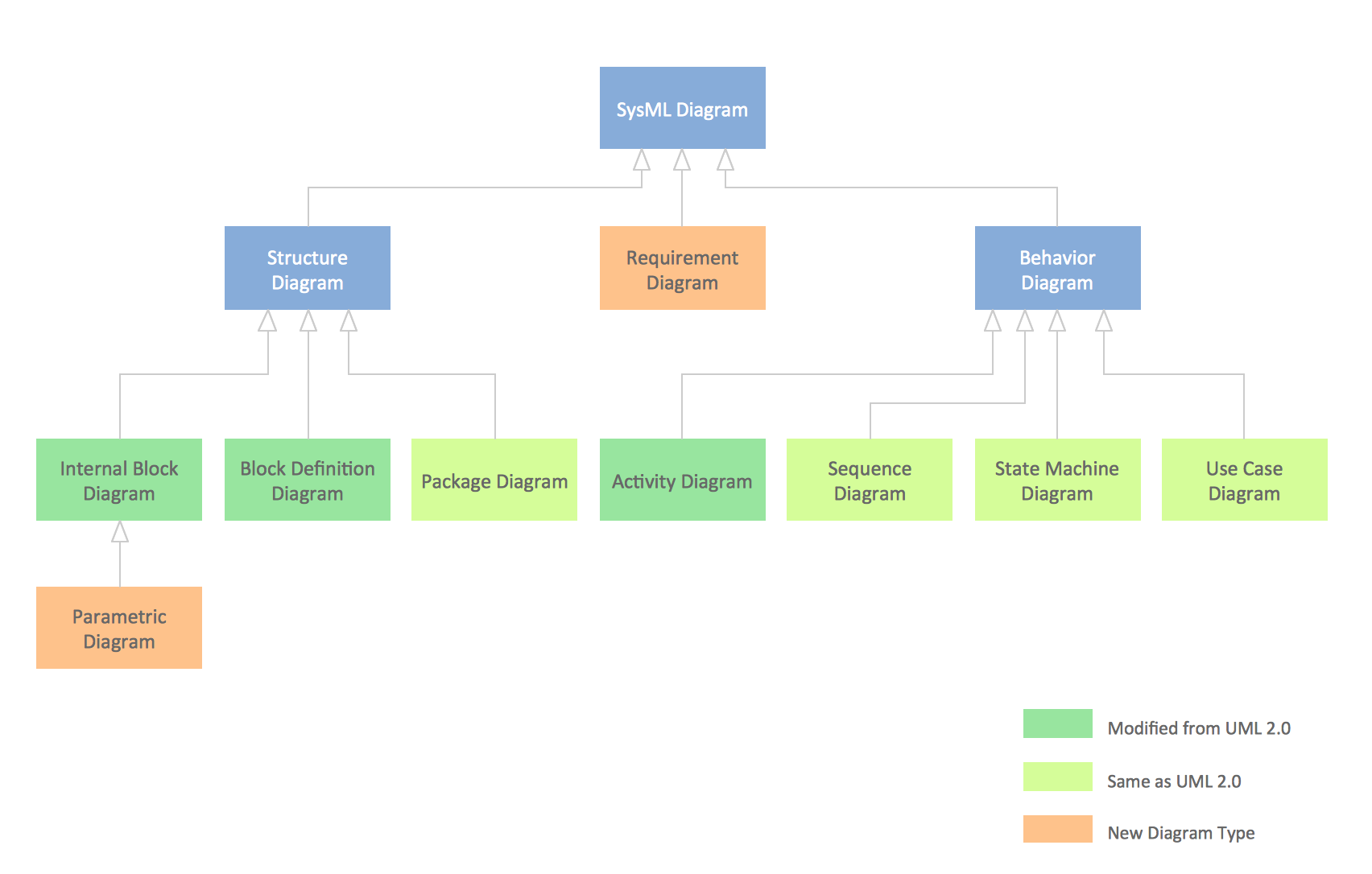
SysML Diagram
- Process Flow Diagram Symbols | Process Flowchart | How to Draw a ...
- Chemical Engineering Drawing Diagram Software
- How to Draw a Chemical Process Flow Diagram | Chemical and ...
- Show How U Can Use A Computer For Flow Sheeting Design
- Chemical Engineering Process Flow Diagram Software Free
- How to Draw a Chemical Process Flow Diagram | Design elements ...
- Chemical and Process Engineering | Top 5 Android Flow Chart ...
- Chemical and Process Engineering | Chemical Engineering ...
- Top 5 Android Flow Chart Apps | Draw Network Diagram based on ...
- Draw A Flow Chart Of Chemical Industries Using Air As Raw Material