Process Flow Diagram Symbols

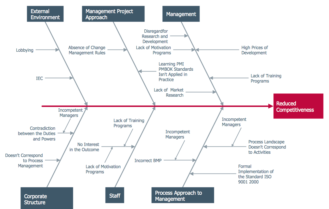
How Do Fishbone Diagrams Solve Manufacturing Problems

Types of Flowcharts


Competitor Analysis

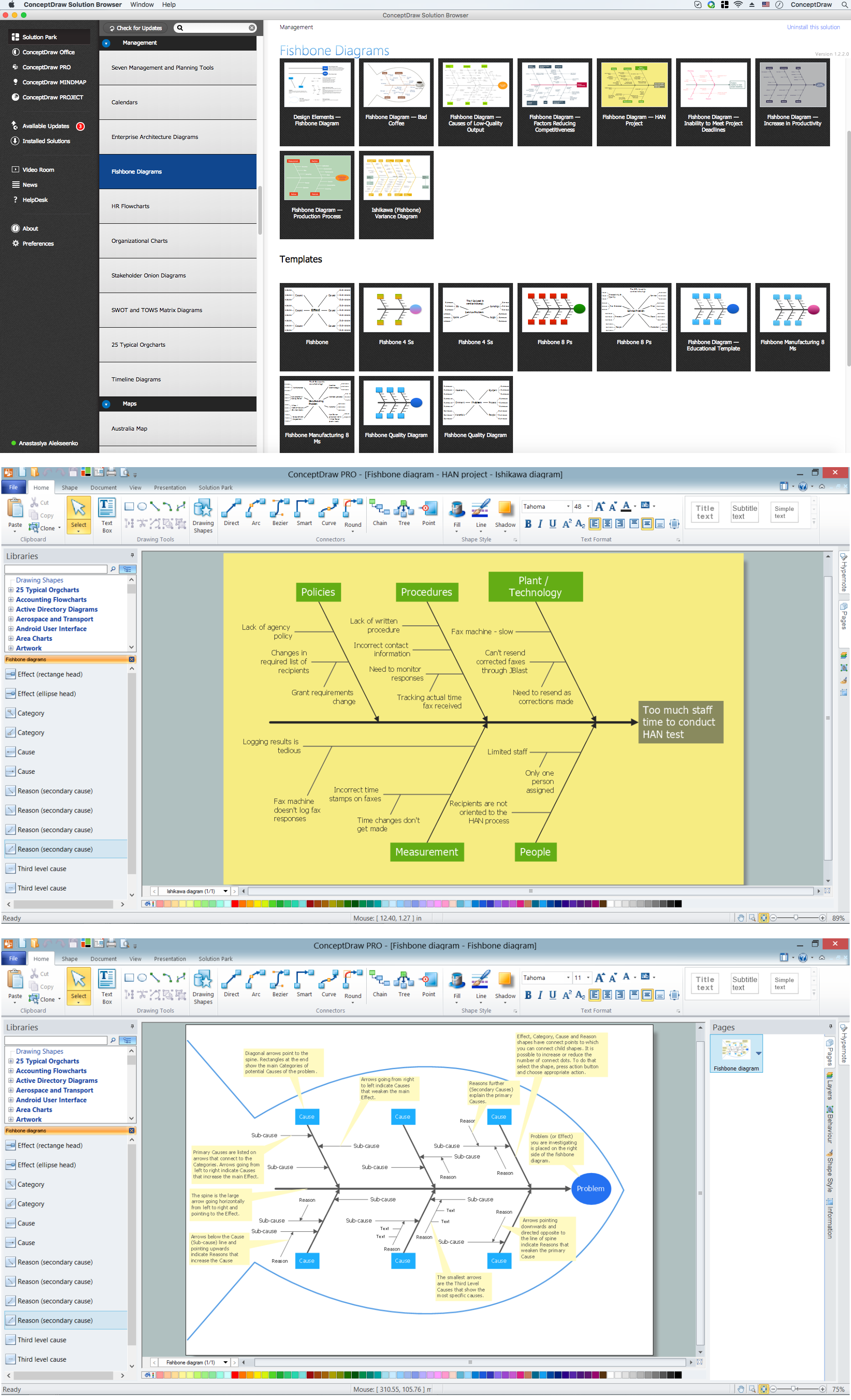
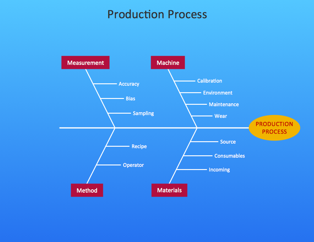
 Fishbone Diagrams
The Fishbone Diagrams solution extends ConceptDraw DIAGRAM software with the ability to easily draw the Fishbone Diagrams (Ishikawa Diagrams) to clearly see the cause and effect analysis and also problem solving. The vector graphic diagrams produced using this solution can be used in whitepapers, presentations, datasheets, posters, and published technical material.
Ishikawa Diagram
Create Fishbone Diagrams
 Chemical and Process Engineering
This chemical engineering solution extends ConceptDraw DIAGRAM.9.5 (or later) with process flow diagram symbols, samples, process diagrams templates and libraries of design elements for creating process and instrumentation diagrams, block flow diagrams (BFD
When To Use a Fishbone Diagram

Cause and Effect Diagram
- Fishbone Diagrams | How Do Fishbone Diagrams Solve ...
- Flow Diagram In Industrial Engineering
- Type Of Flow Diagram Used In Chemical Industries Ppt
- Process Flow Diagram Symbols | How to Create a Mechanical ...
- Flow Diagrams Tqm With Example
- Chemical Industries Flow Chart
- Oil And Gas Process Flow Diagram
- Industrial Process Diagram
- Petrochemical Industry Wih Help Of Process Flow Diagram
- How to Draw a Chemical Process Flow Diagram | Chemical and ...