Circuits and Logic Diagram Software

Wiring Diagrams with ConceptDraw DIAGRAM

Process Flow Diagram

HelpDesk
How to Create a Fault Tree Analysis Diagram (FTD)

Swim Lane Flowchart Symbols

How To use Electrical and Telecom Plan Software


 Electrical Engineering
This solution extends ConceptDraw DIAGRAM.9.5 (or later) with electrical engineering samples, electrical schematic symbols, electrical diagram symbols, templates and libraries of design elements, to help you design electrical schematics, digital and analog
Venn Diagram Examples for Problem Solving. Venn Diagram as a Truth Table

Total Quality Management Definition

Electrical Symbols, Electrical Diagram Symbols

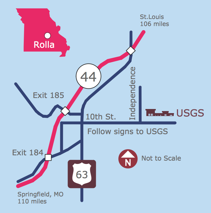
Maps and Directions
Mechanical Design Software

Electrical Symbols — Rotating Equipment

Mechanical Drawing Software

Fault Tree Analysis Software

- Circuits and Logic Diagram Software | Samples of Flowchart ...
- Drawing Flow Chart Diagram For The Logic Gate
- Flow Chart Gates
- Electrical Symbols — Logic Gate Diagram | Design elements - Logic ...
- Electrical Symbols — Logic Gate Diagram | Process Flowchart ...
- Circuits and Logic Diagram Software | Total Quality Management ...
- Logic gate diagram
- Process Flowchart | Electrical Symbols — Logic Gate Diagram ...
- Venn Diagram Template for Word | Logic gate diagram - Template ...
- Electrical Symbols, Electrical Diagram Symbols | Transistor Family ...
- Electrical Symbols — Logic Gate Diagram | How To use House ...
- Electrical Symbols — Logic Gate Diagram | Circuits and Logic ...
- Design elements - Logic gate diagram | Electrical Symbols ...
- Electrical Symbols, Electrical Diagram Symbols | Electrical Symbols ...
- Process Flowchart | Circuits and Logic Diagram Software | Electrical ...
- Circuits and Logic Diagram Software | Electrical Drawing Software ...
- Design elements - Logic gate diagram | Engineering | Process Flow ...
- Basic Flowchart Symbols and Meaning | Symbol Represent ...
- Business diagrams & Org Charts with ConceptDraw PRO | Process ...