Mechanical Drawing Symbols

The vector stencils library "Bearings" contains 59 symbols of ball bearings, roller bearings, shafts, springs, gears, hooks, spindles, and keys.
Use it to design engineering drawings of machine tools and mechanical devices.
"A bearing is a machine element that constrains relative motion and reduce friction between moving parts to only the desired motion. The design of the bearing may, for example, provide for free linear movement of the moving part or for free rotation around a fixed axis; or, it may prevent a motion by controlling the vectors of normal forces that bear on the moving parts. Many bearings also facilitate the desired motion as much as possible, such as by minimizing friction. Bearings are classified broadly according to the type of operation, the motions allowed, or to the directions of the loads (forces) applied to the parts." [Bearing (mechanical). Wikipedia]
The shapes example "Design elements - Bearings" was created using the ConceptDraw PRO diagramming and vector drawing software extended with the Mechanical Engineering solution from the Engineering area of ConceptDraw Solution Park.
Bearing symbols

The vector stencils library "Bearings" contains 59 symbols of ball bearings, roller bearings, shafts, springs, gears, hooks, spindles, and keys.
Use it to design engineering drawings of machine tools and mechanical devices in the ConceptDraw PRO diagramming and vector drawing software extended with the Mechanical Engineering solution from the Engineering area of ConceptDraw Solution Park.
www.conceptdraw.com/ solution-park/ engineering-mechanical
Through hole
Threaded hole 3
Threaded hole 4
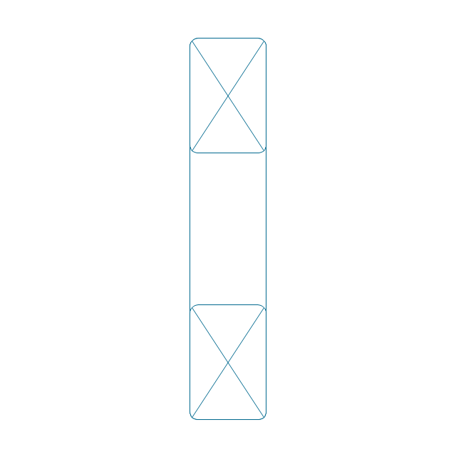
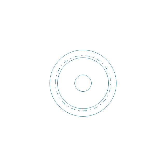
Rolling bearings 2
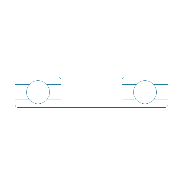
Rolling bearings
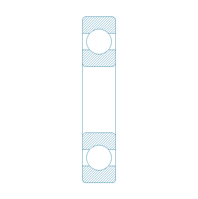
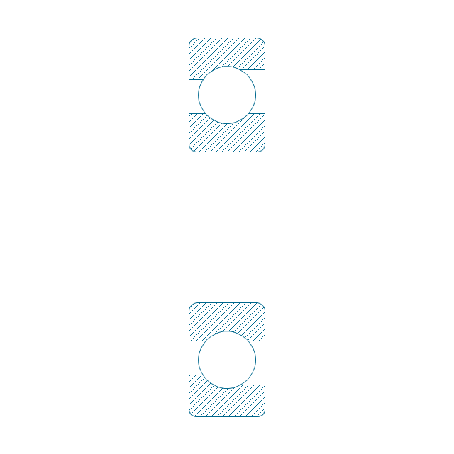
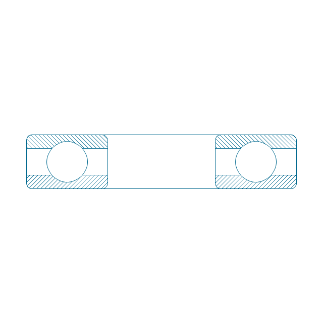
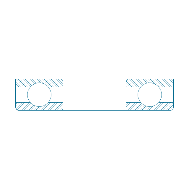
Deep groove ball bearing, hatched
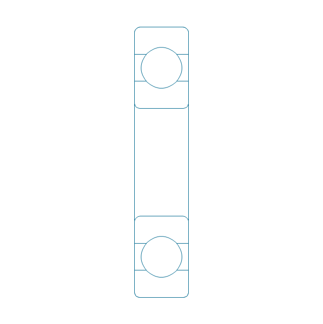
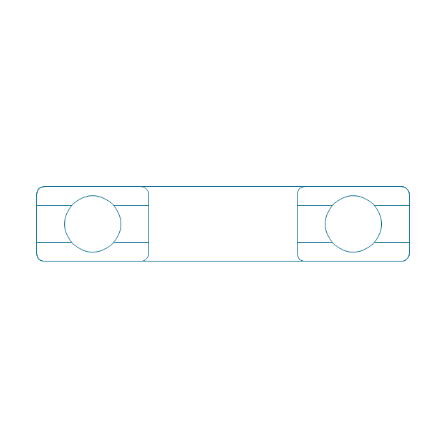
Deep groove ball bearing, unhatched
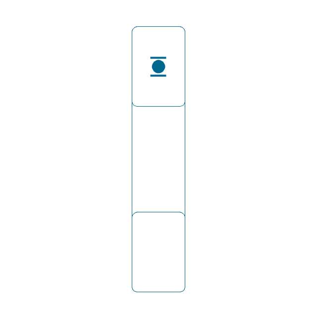
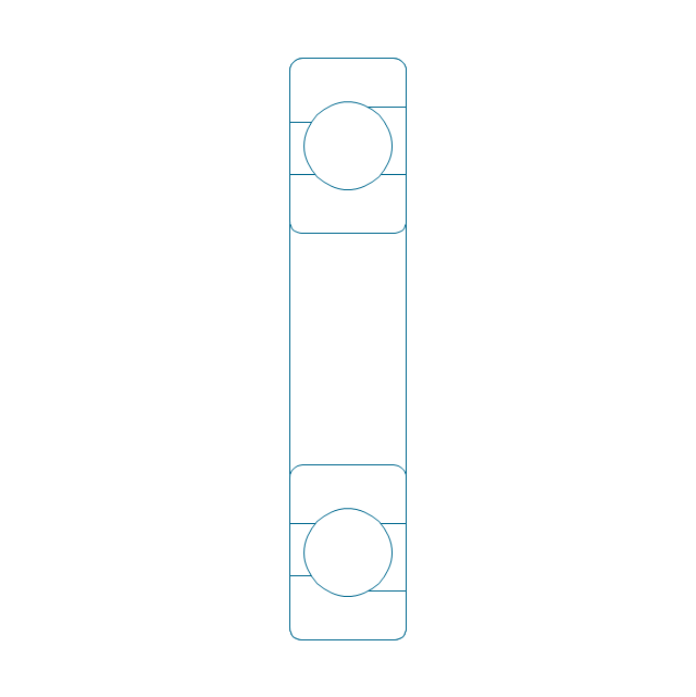
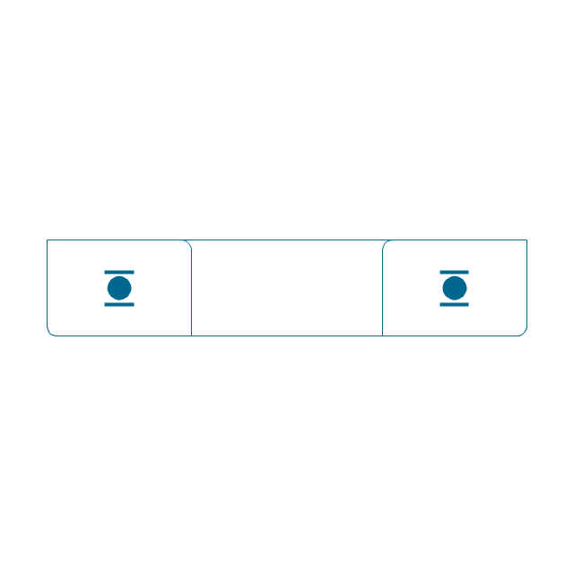
Deep groove ball bearing, simpl.
Angular contact ball bearing, simpl.
Angular contact ball bearing, unhatched
Angular contact ball bearing, hatched
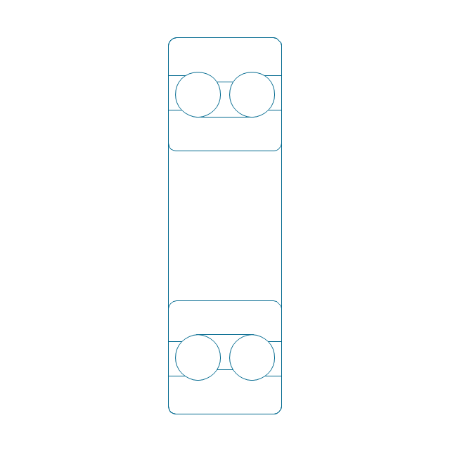
Angular contact ball bearing dbl, unhatched
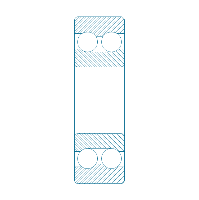
Angular contact ball bearing dbl, hatched
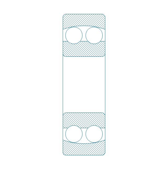
Self align. dbl ball bearing, hatched
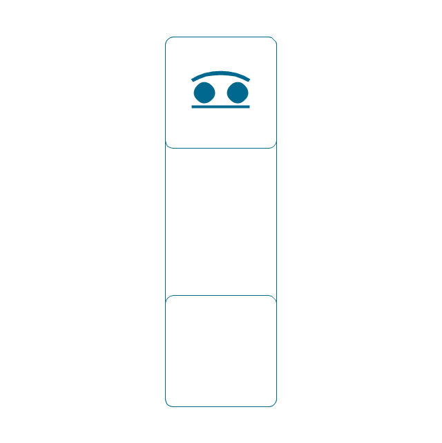
Self align. dbl bearing, simpl.
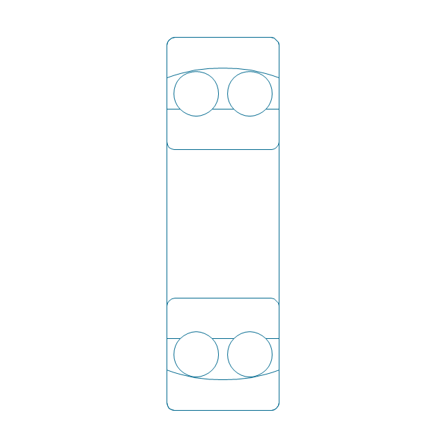
Self align. dbl ball bearing, unhatched
Thrust ball bearing, hatched
Thrust ball bearing, unhatched
Thrust ball bearing, simpl.
Thrust ball bearing, hatched 2
Thrust ball bearing, unhatched 2
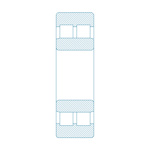
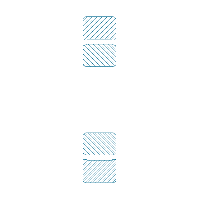
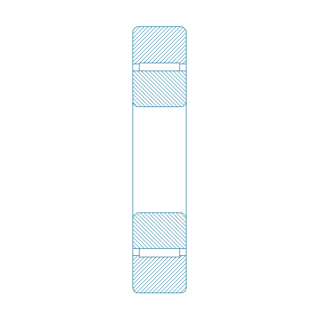
Cylindrical roller bearing, hatched
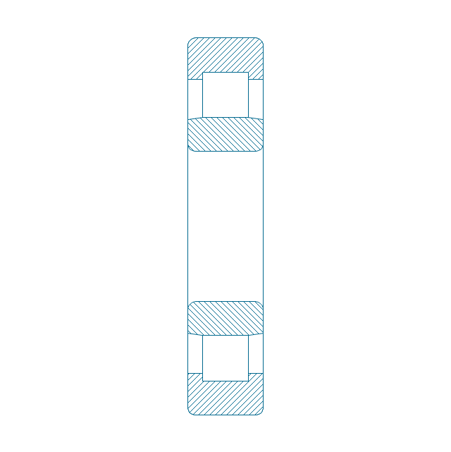
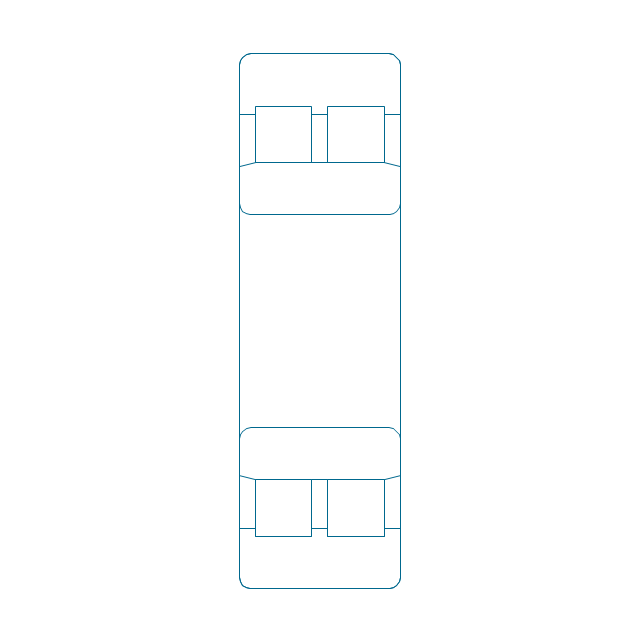
Cylindrical roller bearing, unhatched
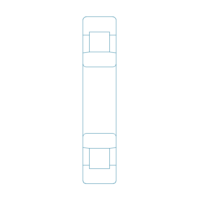
Cylindrical roller bearing, simpl.
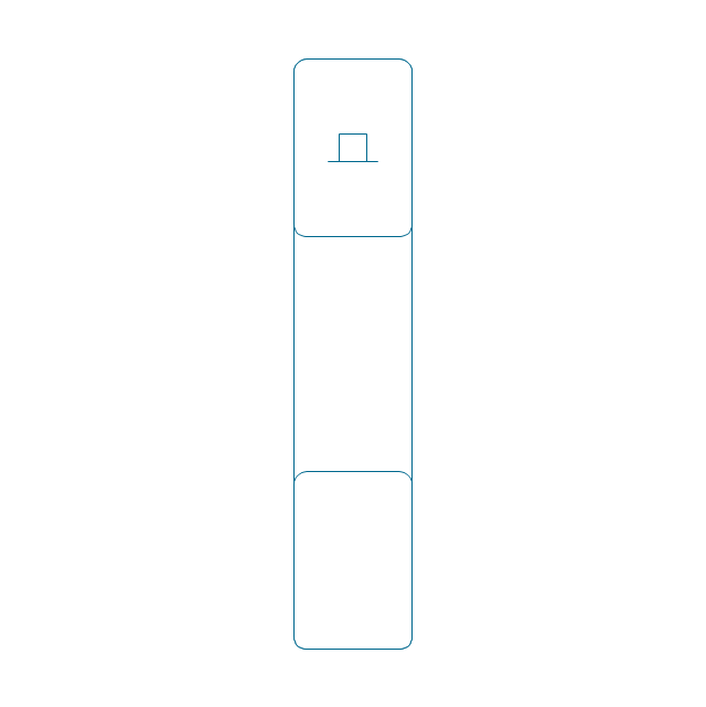
Cylindrical roller bearing dbl, simpl.
Cylindrical roller bearing dbl, unhatched
Cylindrical roller bearing dbl, hatched
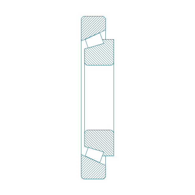
Taper roller bearing, hatched
Taper roller bearing, unhatched
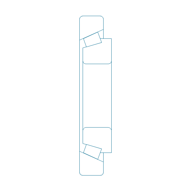
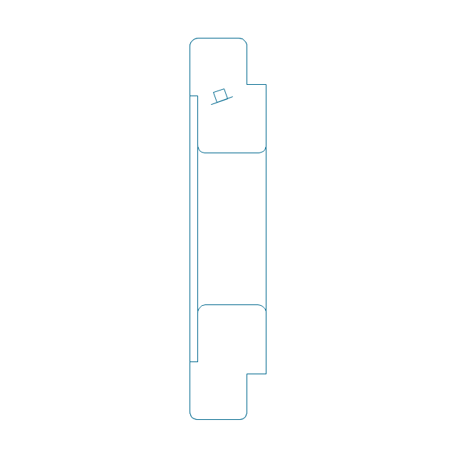
Taper roller bearing, simpl.
Needle roller bearing, hatched
Needle roller bearing, hatched 2
Needle roller bearing, unhatched
Needle roller bearing, unhatched 2
Needle roller bearing, simpl.
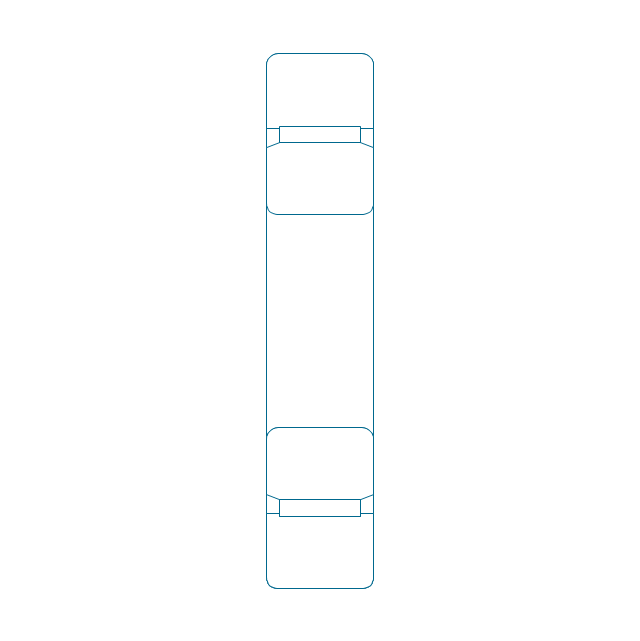
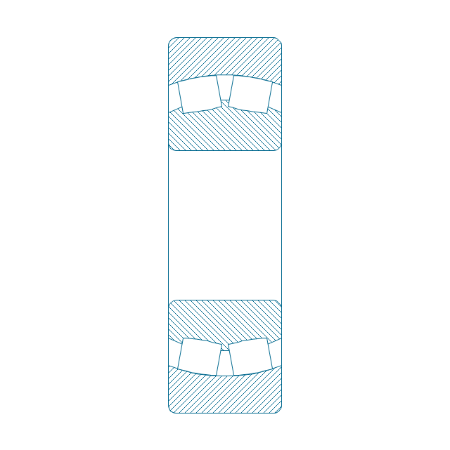
Spher. roller bearing dbl, hatched 2
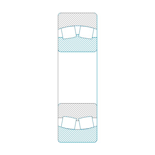
Spher. roller bearing dbl, hatched
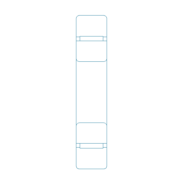
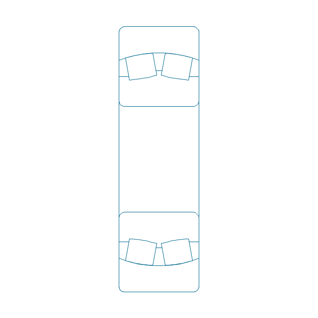
Spher. roller bearing dbl, unhatched
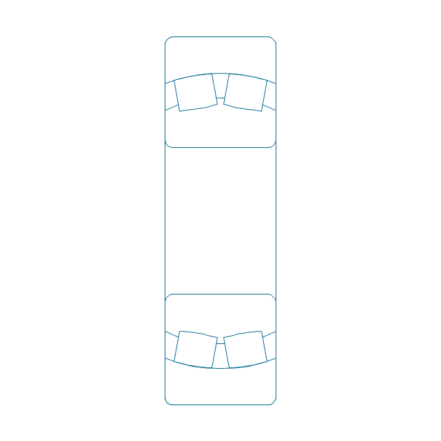
Spher. roller bearing dbl, unhatched 2
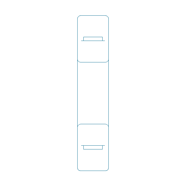
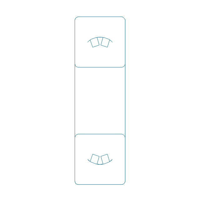
Spher. roller bearing dbl, simpl.
Gear
Gear (web)
-bearings---vector-stencils-library.png--diagram-flowchart-example.png)
Gear (keyway)
-bearings---vector-stencils-library.png--diagram-flowchart-example.png)
Gear (web, keyway)
-bearings---vector-stencils-library.png--diagram-flowchart-example.png)
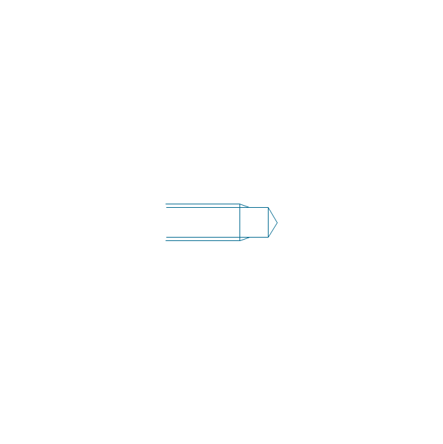
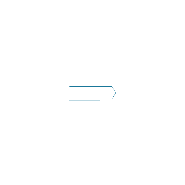
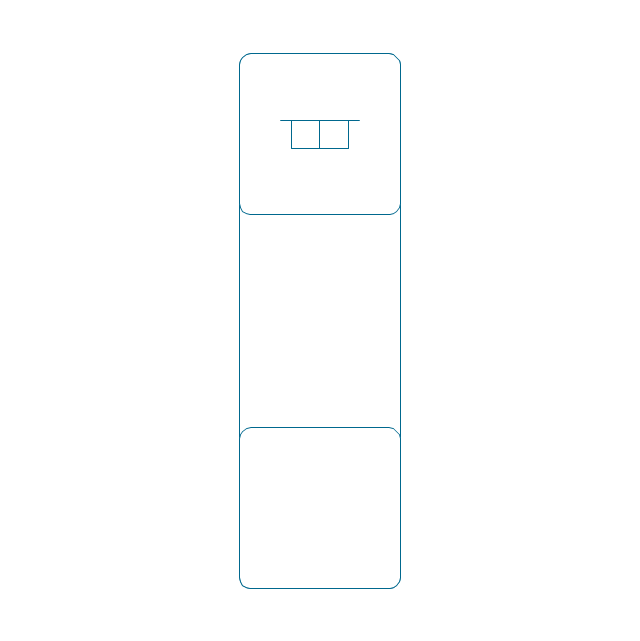
Tapered shaft
Tapered key
Tapered key (gib head)
-bearings---vector-stencils-library.png--diagram-flowchart-example.png)
Tapered shaft
Hole chamfer
Shaft chamfer
Undercut
Centering bore
Cutaway
Spindle end
Spindle end (bore)
-bearings---vector-stencils-library.png--diagram-flowchart-example.png)
Countersunk hole

Countersunk hole 2

Threaded hole

Threaded hole 2

The design elements library Walls, shell and structure contains 29 symbols of structural elements: walls, rooms, windows, doors, pillars.
Use the vector stencils library Walls, shell and structure to draw the floor plans and other architectural drawings, blueprints, home and building interior design, space layout plans, construction and house framing diagrams using the ConceptDraw PRO diagramming and vector drawing software.
"A wall is a horizontal structure, usually solid, that defines and sometimes protects an area. Most commonly, a wall delineates a building and supports its superstructure, separates space in buildings into sections, or protects or delineates a space in the open air. There are three principal types of structural walls: building walls, exterior boundary walls, and retaining walls.
Building walls have one main purpose: to support roofs and ceilings. Such walls most often have three or more separate components. In today's construction, a building wall will usually have the structural elements (such as 2×4 studs in a house wall), insulation, and finish elements or surface (such as drywall or panelling). In addition, the wall may house various types of electrical wiring or plumbing. Electrical outlets are usually mounted in walls.
Building walls frequently become works of art externally and internally, such as when featuring mosaic work or when murals are painted on them; or as design foci when they exhibit textures or painted finishes for effect.
In architecture and civil engineering, the term curtain wall refers to the facade of a building which is not load-bearing but functions as decoration, finish, front, face, or history preservation." [Wall. Wikipedia]
This shapes library Walls, shell and structure is provided by the Floor Plans solution from the Building Plans area of ConceptDraw Solution Park.

Mechanical Design Software

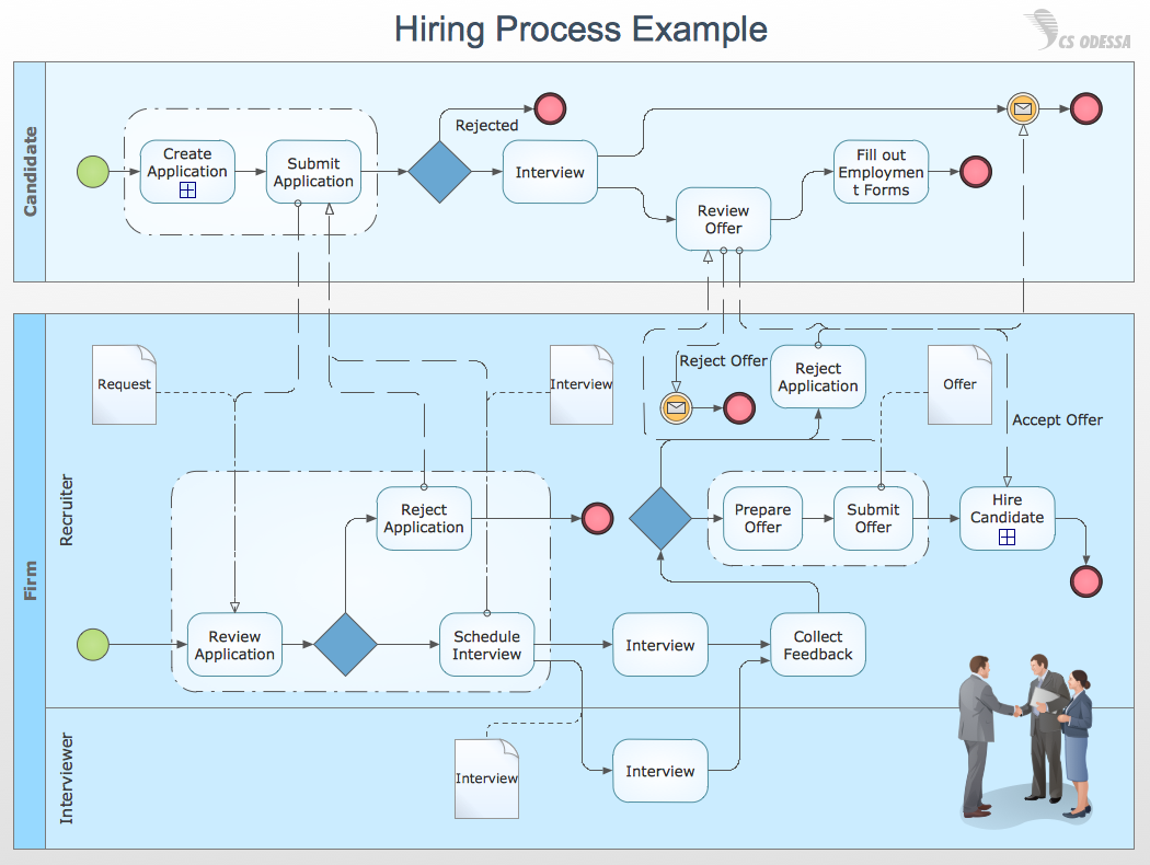
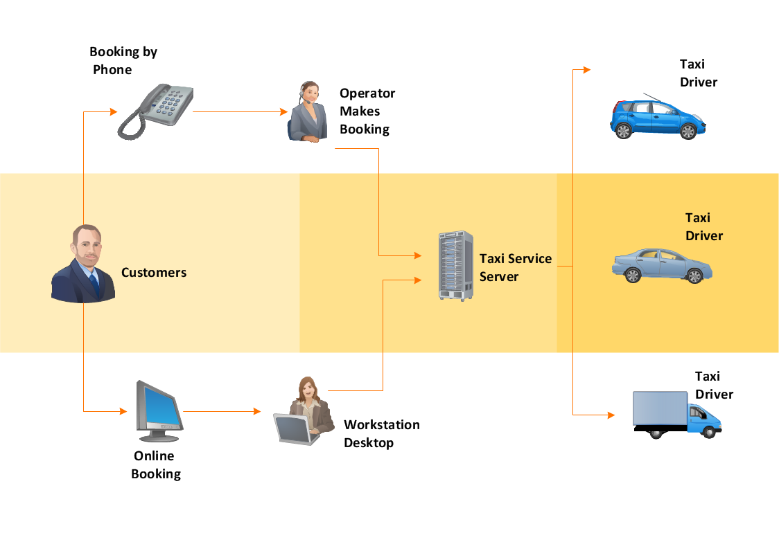
How to Draw Business Process Diagrams with RapidDraw Interface
Technical Drawing Software

CAD Drawing Software for Making Mechanic Diagram and Electrical Diagram Architectural Designs


Influence Diagram

Mechanical Engineering

Workflow Diagram
Technical Drawing Software

 Mechanical Engineering
This solution extends ConceptDraw DIAGRAM.9 mechanical drawing software (or later) with samples of mechanical drawing symbols, templates and libraries of design elements, for help when drafting mechanical engineering drawings, or parts, assembly, pneumatic,
Mechanical Drawing Software

Decision Making

- Design elements - Bearings | Mechanical Drawing Symbols ...
- Mechanical Drawing Symbols | Design elements - Bearings ...
- Mechanical Drawing Symbols | Design elements - Bearings ...
- Mechanical Drawing Symbols | Design elements - Bearings ...
- Design elements - Bearings | Basic Flowchart Symbols and Meaning ...
- Conventional Representation Or Symbol Of Bearing
- Mechanical Drawing Symbols | Mechanical Engineering | Design ...
- Bearing Representation Symbol
- Mechanical Drawing Symbols | Design elements - Bearings | How to ...
- Type Of Bearing With Sketched Diagram
- Design elements - Bearings | Mechanical Drawing Symbols | Design ...
- Mechanical Drawing Symbols | Design elements - Bearings ...
- Types Of Bearings And Its Conventional Representation
- Symbol For Bearing On Shaft
- Mechanical Drawing Symbols | Design elements - Bearings ...
- Bearing Symbol In Diagram
- Mechanical Drawing Symbols | Design elements - Bearings | Design ...
- Process Flowchart | Technical Drawing Software | Electrical Symbols ...
- Types Of Bearing And Its Conventional Represent Ation Com
- Design elements - Walls, shell and structure | Bearing Symbol ...