The vector stencils library "Qualifying" contains 56 qualifying symbols of radiation, polarity, phase, windings, wire, ground, connection, connector, coaxial, electret.
Use these signs to annotate or specify characteristics of objects in electrical drawings, electronic schematics, circuit diagrams, electromechanical drawings, and wiring diagrams, cabling layout diagrams.
"An electrical drawing, is a type of technical drawing that shows information about power, lighting, and communication for an engineering or architectural project. Any electrical working drawing consists of "lines, symbols, dimensions, and notations to accurately convey an engineering's design to the workers, who install the electrical system on the job".
A complete set of working drawings for the average electrical system in large projects usually consists of:
(1) A plot plan showing the building's location and outside electrical wiring.
(2) Floor plans showing the location of electrical systems on every floor.
(3) Power-riser diagrams showing panel boards.
(4) Control wiring diagrams.
(5) Schedules and other information in combination with construction drawings.
Electrical drafters prepare wiring and layout diagrams used by workers who erect, install, and repair electrical equipment and wiring in communication centers, power plants, electrical distribution systems, and buildings." [Electrical drawing. Wikipedia]
The signs example "Design elements - Qualifying" was drawn using the ConceptDraw PRO diagramming and vector drawing software extended with the Electrical Engineering solution from the Engineering area of ConceptDraw Solution Park.
Qualifying symbols

Electrical Drawing Software and Electrical Symbols

Electrical and Telecom Plan Software

The design elements library Walls, shell and structure contains 29 symbols of structural elements: walls, rooms, windows, doors, pillars.
Use the vector stencils library Walls, shell and structure to draw the floor plans and other architectural drawings, blueprints, home and building interior design, space layout plans, construction and house framing diagrams using the ConceptDraw PRO diagramming and vector drawing software.
"A wall is a horizontal structure, usually solid, that defines and sometimes protects an area. Most commonly, a wall delineates a building and supports its superstructure, separates space in buildings into sections, or protects or delineates a space in the open air. There are three principal types of structural walls: building walls, exterior boundary walls, and retaining walls.
Building walls have one main purpose: to support roofs and ceilings. Such walls most often have three or more separate components. In today's construction, a building wall will usually have the structural elements (such as 2×4 studs in a house wall), insulation, and finish elements or surface (such as drywall or panelling). In addition, the wall may house various types of electrical wiring or plumbing. Electrical outlets are usually mounted in walls.
Building walls frequently become works of art externally and internally, such as when featuring mosaic work or when murals are painted on them; or as design foci when they exhibit textures or painted finishes for effect.
In architecture and civil engineering, the term curtain wall refers to the facade of a building which is not load-bearing but functions as decoration, finish, front, face, or history preservation." [Wall. Wikipedia]
This shapes library Walls, shell and structure is provided by the Floor Plans solution from the Building Plans area of ConceptDraw Solution Park.

The vector stencils library "Electrical and telecom" contains 83 symbols of electrical and telecommunication equipment for electrical drawings and wiring diagrams of buildings, communication centers, power plants and electrical distribution systems.
"An electrical drawing, is a type of technical drawing that shows information about power, lighting, and communication for an engineering or architectural project." [Electrical drawing. Wikipedia]
Use the design elements library "Electrical and telecom" to design your own electrical drawings, plot plans of the building outside electrical wiring, floor plans with electrical and telecommunication systems layout, power-riser diagrams with panel boards, control wiring diagrams and cabling layout schemes, reflected ceiling plans and lighting panels layouts using the ConceptDraw PRO diagramming and vector drawing software.
The shapes library "Electrical and telecom" is included in the Electric and Telecom Plans solution from the Building Plans area of ConceptDraw Solution Park.
Electrical and telecom symbols

HelpDesk
How to Create an Azure Architecture Diagram Using ConceptDraw PRO

How To use House Electrical Plan Software


Technical Drawing Software

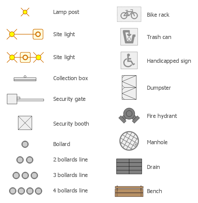
The design elements library Site accessories contains 18 symbols of vehicle access control equipment (tollbooth, tollgate, parking fees payment box), a handicapped sign, outdoor lighting, and garbage receptacles.
"A site plan is an architectural plan, landscape architecture document, and a detailed engineering drawing of proposed improvements to a given lot. A site plan usually shows a building footprint, travelways, parking, drainage facilities, sanitary sewer lines, water lines, trails, lighting, and landscaping and garden elements." [Site plan. Wikipedia]
Use the Site accessories library to design plans, equipment layouts and maps of sites, parking lots, residential and commercial landscapes, parks, yards, plats, outdoor recreational facilities, and irrigation systems using ConceptDraw PRO diagramming and vector drawing software.
The design elements library Site accessories is contained in the Site Plans solution from the Building Plans area of ConceptDraw Solution Park.
This cafe electrical floor plan sample shows the outlet and switch layout.
"An electrical drawing, is a type of technical drawing that shows information about power, lighting, and communication for an engineering or architectural project. Any electrical working drawing consists of "lines, symbols, dimensions, and notations to accurately convey an engineering's design to the workers, who install the electrical system on the job".
A complete set of working drawings for the average electrical system in large projects usually consists of:
(1) A plot plan showing the building's location and outside electrical wiring.
(2) Floor plans showing the location of electrical systems on every floor.
(3) Power-riser diagrams showing panel boards.
(4) Control wiring diagrams.
(5) Schedules and other information in combination with construction drawings.
Electrical drafters prepare wiring and layout diagrams used by workers who erect, install, and repair electrical equipment and wiring in communication centers, power plants, electrical distribution systems, and buildings." [Electrical drawing. Wikipedia]
The outlet and switch layout example "Cafe electrical floor plan" was created using the ConceptDraw PRO diagramming and vector drawing software extended with the Electric and Telecom Plans solution from the Building Plans area of ConceptDraw Solution Park.
Outlet and switch layout

How To Draw Building Plans


 Plumbing and Piping Plans
Plumbing and Piping Plans solution extends ConceptDraw PRO v10.2.2 software with samples, templates and libraries of pipes, plumbing, and valves design elements for developing of water and plumbing systems, and for drawing Plumbing plan, Piping plan, PVC Pipe plan, PVC Pipe furniture plan, Plumbing layout plan, Plumbing floor plan, Half pipe plans, Pipe bender plans.
 ConceptDraw Solution Park
ConceptDraw Solution Park collects graphic extensions, examples and learning materials
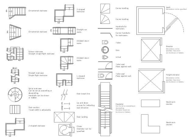
The design elements library Building core contains 80 symbols of stairs, elevators, escalators, restroom fixtures, and a safe.
Use the shapes library Building core to draw the structural diagrams, bathroom layouts, building automation, architectural drawings, and riser diagrams, as well as space plans, store and shopping mall plans, and facility planning, plant layouts using the ConceptDraw PRO diagramming and vector drawing software.
"In architecture and building engineering, a floor plan otherwise known as a Scottish plan is a drawing to scale, showing a view from above, of the relationships between rooms, spaces and other physical features at one level of a structure.
The term may be used in general to describe any drawing showing the physical layout of objects.
A floor plan could show:
Interior walls and hallways;
Restrooms;
Windows and doors;
Appliances such as stoves, refrigerators, water heater etc.;
Interior features such as fireplaces, saunas and whirlpools;
The use of all rooms shall be indicated." [Floor plan. Wikipedia]
The vector stencils library Building core is provided by the Floor Plans solution from the Building Plans area of ConceptDraw Solution Park.
- Symbol Of Architectural Engineering System
- Mechanic Symbols
- Architectural Electrical Drafting Symbol
- Design elements - Building core | Refrigerator Architectural Symbol
- Architectural Sanitary Symbols Pdf
- Electrical Drawing Software | How To use House Electrical Plan ...
- Design elements - Qualifying | Zigzag Symbol On Architect Plan
- Architectural Electrical Symbols
- Industrial Electrical Symbols
- Drawing Electrical Symbols
- Electrical Symbols Com
- Landscape Architecture Drawing Symbols
- Bench Symbol Architectural
- Electrical Diagrams Symbols
- Design elements - Electrical and telecom | Architectural Symbol For ...
- How to Create an Electrical Diagram | Mechanical Engineering ...
- Circuit Of Architectural Engineering System
- Elements location of a welding symbol | Mechanical Engineering ...
- Civil Engineering Drawing Symbols Chart For Bulding
- Mechanical Industries Drawings Symbols