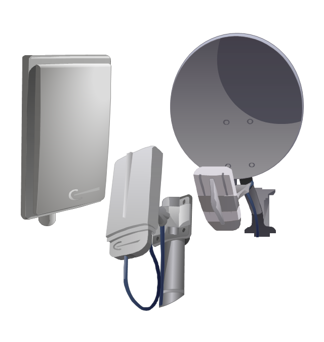
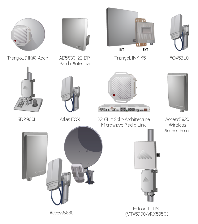
The vector stencils library "Trango" contains 10 clipart icons of Trango devices for drawing computer network diagrams and telecommunication equipment layouts.
"Trango Systems, Inc., was founded in 1996 and is headquartered in San Diego County, California. ...
Trango Systems microwave backhaul solutions and products are used in cellular/ mobile backhaul, Enterprise LAN/ WAN Bridging, All-IP Service Provider Networks, and Government/ Municipal applications." [trangosys.com]
The clip art example "Trango - Vector stencils library" was created using the ConceptDraw PRO diagramming and vector drawing software extended with the Telecommunication Network Diagrams solution from the Computer and Networks area of ConceptDraw Solution Park.
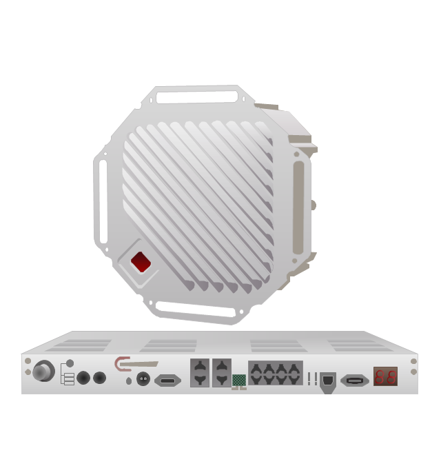
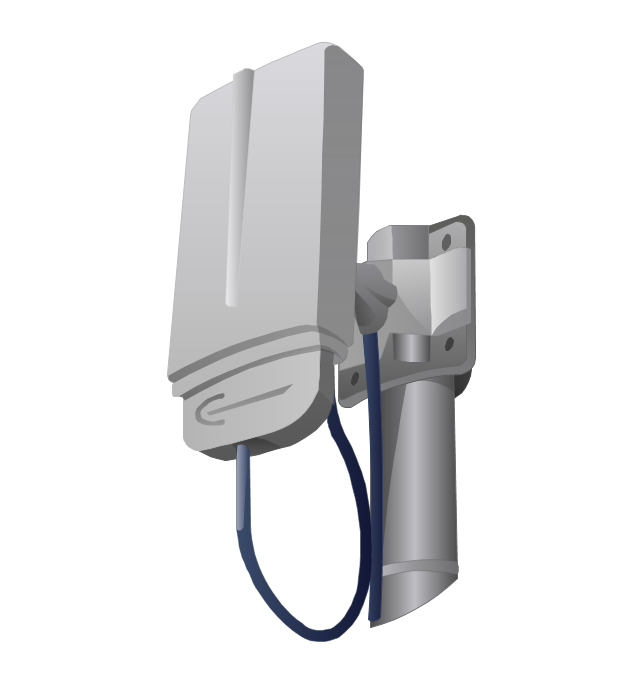
TrangoLINK Apex microwave RF link
TrangoLINK Giga digital microwave radio backhaul
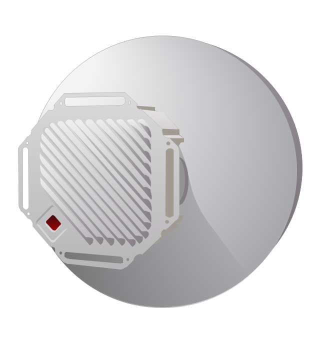
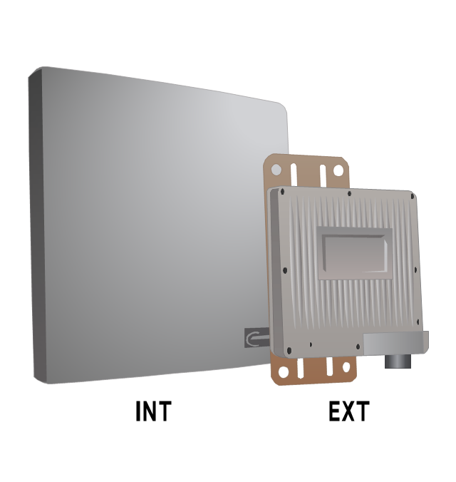
Trango AD5830-23-DP broadband antenna
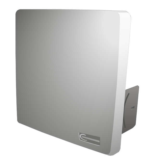
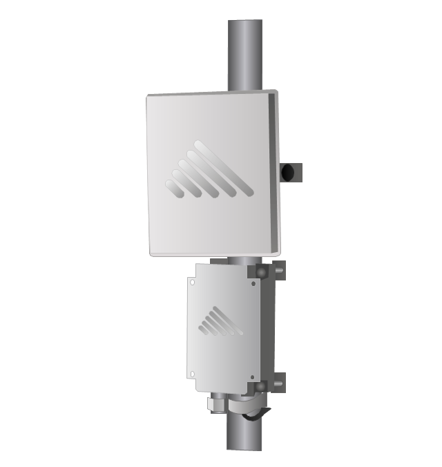
Access5830 wireless access point
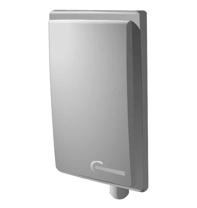
TrangoLINK-45 point-to-point wireless Ethernet bridge
Falcon PLUS wireless video/audio system
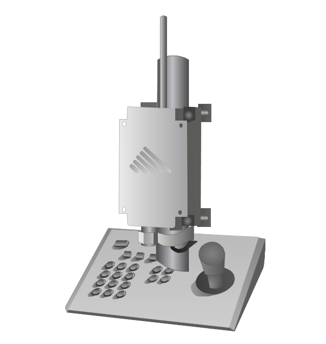
SDR900H PTZ camera control system
FOX5310 subscriber unit
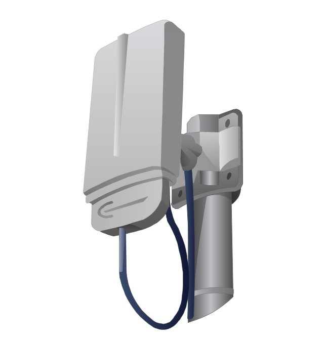
Atlas FOX subscriber unit
Access5830 dual-band wireless Ethernet system
Cisco Network Topology. Cisco icons, shapes, stencils and symbols

The vector stencils library "VHF UHF SHF" contains 52 symbols for VHF, UHF, and SHF circuit design, including capacitance measurers, nonreciprocal devices, modulators, phase shifters, field polarization devices, and filters.
"Very high frequency (VHF) is the ITU-designated range of radio frequency electromagnetic waves from 30 MHz to 300 MHz, with corresponding wavelengths of one to ten meters. Frequencies immediately below VHF are denoted high frequency (HF), and the next higher frequencies are known as ultra high frequency (UHF).
Common uses for VHF are FM radio broadcasting, television broadcasting, land mobile stations (emergency, business, private use and military), long range data communication up to several tens of kilometres with radio modems, amateur radio, and marine communications. Air traffic control communications and air navigation systems (e.g. VOR, DME & ILS) work at distances of 100 kilometres or more to aircraft at cruising altitude.
VHF was previously used for analog television stations in the US." [Very high frequency. Wikipedia]
"Ultra-high frequency (UHF) designates the ITU radio frequency range of electromagnetic waves between 300 MHz and 3 GHz (3,000 MHz), also known as the decimetre band or decimetre wave as the wavelengths range from one to ten decimetres; that is 1 decimetre to 1 metre. Radio waves with frequencies above the UHF band fall into the SHF (super-high frequency) or microwave frequency range. Lower frequency signals fall into the VHF (very high frequency) or lower bands. UHF radio waves propagate mainly by line of sight; they are blocked by hills and large buildings although the transmission through building walls is high enough for indoor reception. They are used for television broadcasting (digital and analogue), cordless phones, walkie-talkies, satellite communication, and numerous other applications.
The IEEE defines the UHF radar band as frequencies between 300 MHz and 1 GHz. Two other IEEE radar band overlap the ITU UHF band: the L band between 1 and 2 GHz and the S band between 2 and 4 GHz." [Ultra high frequency. Wikipedia]
"Super high frequency (or SHF) is the ITU designation for radio frequencies (RF) in the range of 3 GHz and 30 GHz. This band of frequencies is also known as the centimetre band or centimetre wave as the wavelengths range from ten to one centimetres. These frequencies fall within the microwave band, so radio waves with these frequencies are called microwaves. The small wavelength of microwaves allows them to be directed in narrow beams by aperture antennas such as parabolic dishes, so they are used for point-to-point communication and data links, and for radar. This frequency range is used for most radar transmitters, microwave ovens, wireless LANs, cell phones, satellite communication, microwave radio relay links, and numerous short range terrestrial data links. The commencing wireless USB technology will be using approximately 1/ 3 of this spectrum.
Frequencies in the SHF range are often referred to by their IEEE radar band designations: S, C, X, Ku, K, or Ka band, or by similar NATO or EU designations." [Super high frequency. Wikipedia]
The shapes example "Design elements - VHF UHF SHF" was drawn using the ConceptDraw PRO diagramming and vector drawing software extended with the Electrical Engineering solution from the Engineering area of ConceptDraw Solution Park.
VHF, UHF, SHF symbols

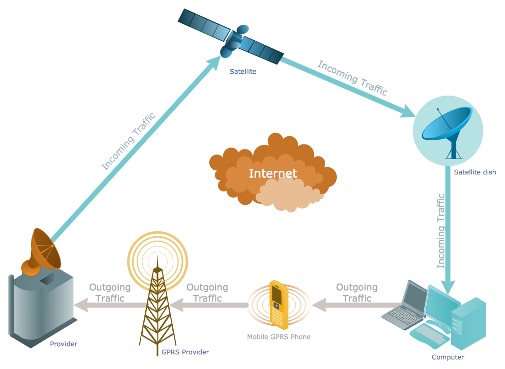
"Satellite Internet access is Internet access provided through communications satellites. ...
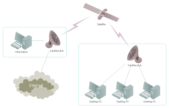
Satellite Internet generally relies on three primary components: a satellite in geostationary orbit (sometimes referred to as a geosynchronous Earth orbit, or GEO), a number of ground stations known as gateways that relay Internet data to and from the satellite via radio waves (microwave), and a VSAT (very-small-aperture terminal) dish antenna with a transceiver, located at the subscriber's premises. Other components of a satellite Internet system include a modem at the user end which links the user's network with the transceiver, and a centralized network operations center (NOC) for monitoring the entire system. Working in concert with a broadband gateway, the satellite operates a Star network topology where all network communication passes through the network's hub processor, which is at the center of the star. With this configuration, the number of remote VSATs that can be connected to the hub is virtually limitless." [Satellite Internet access. Wikipedia]
This satellite telecom network diagram example was created using the ConceptDraw PRO diagramming and vector drawing software extended with the Telecommunication Network Diagrams solution from the Computer and Networks area of ConceptDraw Solution Park.
Satellite telecom network diagram
The vector stencils library "Transmission paths" contains 43 symbols of power transmission paths, electronic circuits, bus connectors and elbows, terminals, junctions, and concentrators.
Use it to annotate electrical diagrams, electronic schematics and circuit diagrams.
"A physical medium in data communications is the transmission path over which a signal propagates.
Many transmission media are used as communications channel.
For telecommunications purposes in the United States, Federal Standard 1037C, transmission media are classified as one of the following:
(1) Guided (or bounded) - waves are guided along a solid medium such as a transmission line.
(2) Wireless (or unguided) - transmission and reception are achieved by means of an antenna.
One of the most common physical medias used in networking is copper wire. Copper wire to carry signals to long distances using relatively low amounts of power. The unshielded twisted pair (UTP) is eight strands of copper wire, organized into four pairs.
Another example of a physical medium is optical fiber, which has emerged as the most commonly used transmission medium for long-distance communications. Optical fiber is a thin strand of glass that guides light along its length.
Multimode and single mode are two types of commonly used optical fiber. Multimode fiber uses LEDs as the light source and can carry signals over shorter distances, about 2 kilometers. Single mode can carry signals over distances of tens of miles.
Wireless media may carry surface waves or skywaves, either longitudinally or transversely, and are so classified.
In both communications, communication is in the form of electromagnetic waves. With guided transmission media, the waves are guided along a physical path; examples of guided media include phone lines, twisted pair cables, coaxial cables, and optical fibers. Unguided transmission media are methods that allow the transmission of data without the use of physical means to define the path it takes. Examples of this include microwave, radio or infrared. Unguided media provide a means for transmitting electromagnetic waves but do not guide them; examples are propagation through air, vacuum and seawater.
The term direct link is used to refer to the transmission path between two devices in which signals propagate directly from transmitters to receivers with no intermediate devices, other than amplifiers or repeaters used to increase signal strength. This term can apply to both guided and unguided media.
A transmission may be simplex, half-duplex, or full-duplex.
In simplex transmission, signals are transmitted in only one direction; one station is a transmitter and the other is the receiver. In the half-duplex operation, both stations may transmit, but only one at a time. In full duplex operation, both stations may transmit simultaneously. In the latter case, the medium is carrying signals in both directions at same time." [Transmission medium. Wikipedia]
The shapes example "Design elements - Transmission paths" was drawn using the ConceptDraw PRO diagramming and vector drawing software extended with the Electrical Engineering solution from the Engineering area of ConceptDraw Solution Park.
Transmission path symbols

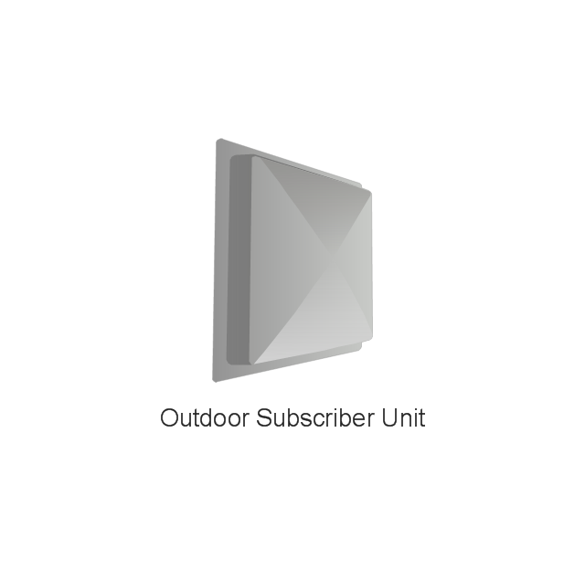
The vector stencils library "Tranzeo" contains 13 clipart icons of Tranzeo devices for drawing computer network diagrams and telecommunication equipment layouts.
"Tranzeo Wireless Technologies Inc. ... leads the wireless broadband industry as a premier manufacturer of high-performance wireless network equipment...
Tranzeo's full spectrum of point-to-point and point-to-multipoint radios, WiMAX equipment, and mesh network solutions are designed for wireless internet service providers, governments, campuses, military, carriers, enterprise customers, and systems integrators..." [tranzeo.com]
The clip art example "Tranzeo - Vector stencils library" was created using the ConceptDraw PRO diagramming and vector drawing software extended with the Telecommunication Network Diagrams solution from the Computer and Networks area of ConceptDraw Solution Park.
www.conceptdraw.com/ solution-park/ computer-networks-telecommunication
Outdoor Subscriber Unit
e Tranzeo TR-WMX-35-i50-W 3.5GHz Indoor Subscriber Unit
EL 500
Pico Base Station
tr6000 Access Point, Point-to-Point, and Client (CPE)
-tranzeo---vector-stencils-library.png--diagram-flowchart-example.png)
WIMAX Solution
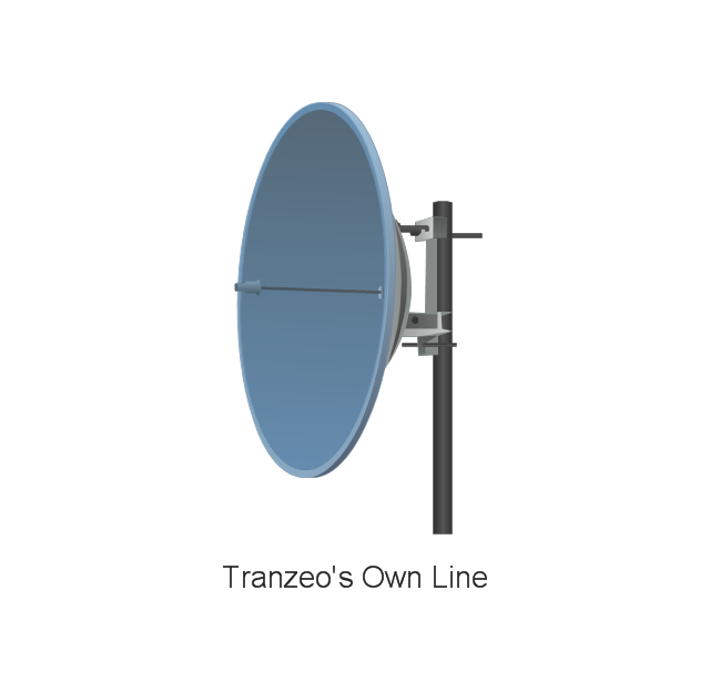
Tranzeo's Own Line of 5.8 GHz Panel Antenna
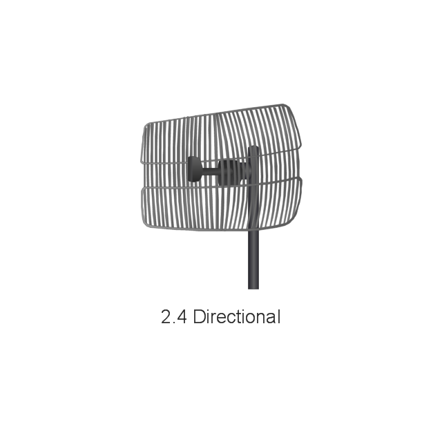
2.4 Directional
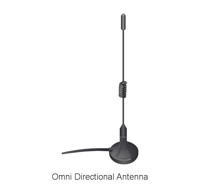
Omni Directional Antenna
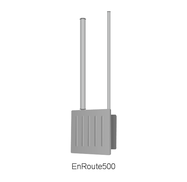
EnRoute500 Wireless Mesh Router
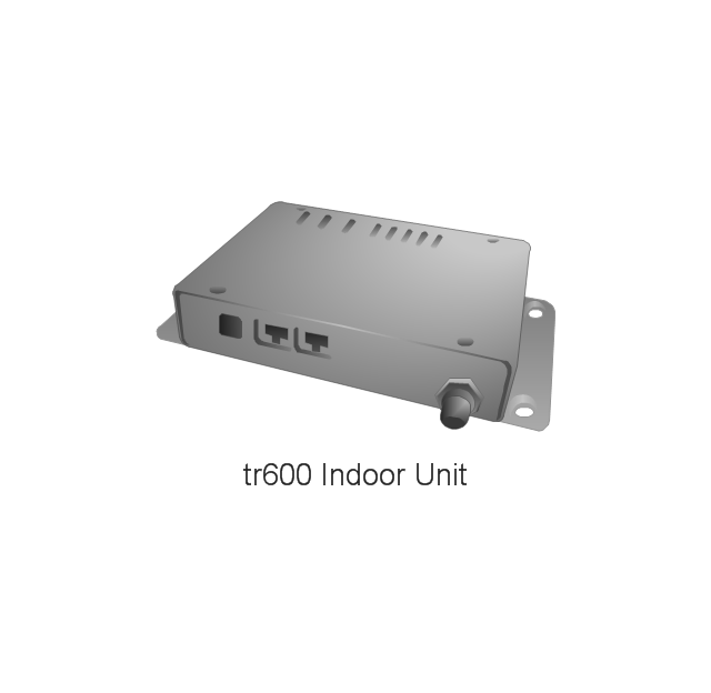
tr600 802.11b/g Indoor Unit
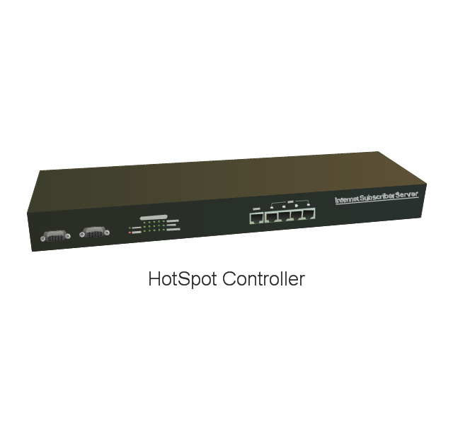
HotSpot Controller
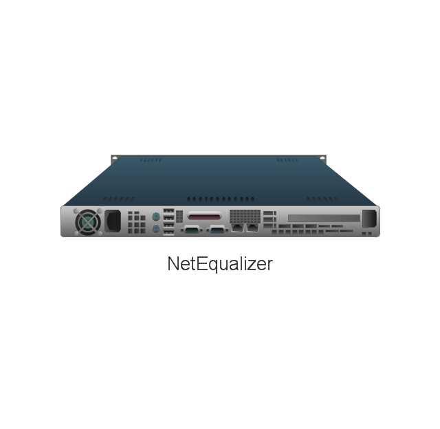
NetEqualizer
Electrical Symbols — Transmission Paths
The vector stencils library "Telecom" contains 20 telecommunication icons. Use it to design your IT and telecom illustrations and infographics with ConceptDraw PRO diagramming and vector drawing software.
"Telecommunication is the transmission of signs, signals, writings, images and sounds or intelligence of any nature by wire, radio, optical or other electromagnetic systems, as defined by the International Telecommunication Union (ITU).
Telecommunication occurs when the exchange of information between communication participants includes the use of technology. It is transmitted either electrically over physical media, such as cables, or via electromagnetic radiation. Such transmission paths are often divided into communication channels which afford the advantages of multiplexing. ...
Modern technologies for long-distance communication usually involve electrical and electromagnetic technologies, such as telegraph, telephone, and teleprinter, networks, radio, microwave transmission, fiber optics, and communications satellites." [Telecommunication. Wikipedia]
The telecommunication icon set example "Design elements - Telecom" is included in the Computers and Communications solution from the Illustration area of ConceptDraw Solution Park.
Telecommunication icon set
Trango Systems microwave backhaul solutions and products are used in cellular/ mobile backhaul, Enterprise LAN/ WAN Bridging, All-IP Service Provider Networks, and Government/ Municipal applications. [trangosys.com]
The example "Design elements - Trango" was created using the ConceptDraw PRO diagramming and vector drawing software extended with the Telecommunication Network Diagrams solution from the Computer and Networks area of ConceptDraw Solution Park.
The example "Design elements - Trango" was created using the ConceptDraw PRO diagramming and vector drawing software extended with the Telecommunication Network Diagrams solution from the Computer and Networks area of ConceptDraw Solution Park.
Telecom equipment
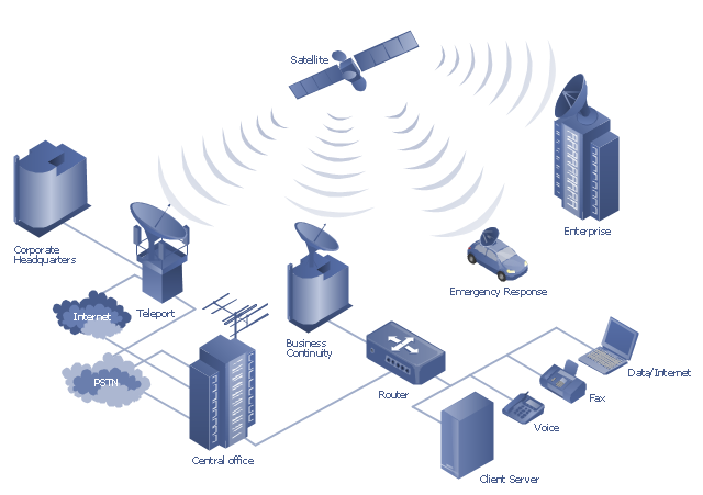
"A communications satellite or comsat is an artificial satellite sent to space for the purpose of telecommunications. Modern communications satellites use a variety of orbits including geostationary orbits, Molniya orbits, elliptical orbits and low (polar and non-polar) Earth orbits.
For fixed (point-to-point) services, communications satellites provide a microwave radio relay technology complementary to that of communication cables. They are also used for mobile applications such as communications to ships, vehicles, planes and hand-held terminals, and for TV and radio broadcasting." [Communications satellite. Wikipedia]
"Satellite telecommunication services:
Satellite crop monitoring,
Satellite Internet access,
Satellite navigation,
Satellite phone,
Satellite radio,
Satellite television." [Satellite. Wikipedia]
This hybrid satellite and common carrier network diagram example was created using the ConceptDraw PRO diagramming and vector drawing software extended with the Telecommunication Network Diagrams solution from the Computer and Networks area of ConceptDraw Solution Park.
Satellite network diagram
Electrical Symbols — VHF UHF SHF

Electrical Symbols — Qualifying

Telecommunications Networks
Telecommunications Network
Vehicular Network
- Tower Antenna Microwave Png
- Design elements - Telecom | Microwave Tower Png
- Microwave Tower Icon Png
- Network Icons | Trango - Vector stencils library | Ptz Icon Png
- Building Networks | Network Glossary Definition | Bases Tation Png
- Military Wireless Tower Png
- Television Png
- Scheme Microwave Antenna Tower
- Microwave Tower Design
- Microwave Transmission Icon Png
- Radar Dish Png
- Radio Transmitter Tower Clip Art Png
- Microwave Antenna Icon
- Microwave Dish Antenna Icon
- Wireless Wave Png
- Icon For Microwave Dish
- Base Station Png
- Microwave Antenna Clipart
- Cisco Network Topology. Cisco icons, shapes, stencils and symbols ...