Electrical Symbols, Electrical Diagram Symbols

Electrical Symbols — Power Sources

Electrical Symbols — Terminals and Connectors

How To use House Electrical Plan Software


This cafe electrical floor plan sample shows the outlet and switch layout.
"An electrical drawing, is a type of technical drawing that shows information about power, lighting, and communication for an engineering or architectural project. Any electrical working drawing consists of "lines, symbols, dimensions, and notations to accurately convey an engineering's design to the workers, who install the electrical system on the job".
A complete set of working drawings for the average electrical system in large projects usually consists of:
(1) A plot plan showing the building's location and outside electrical wiring.
(2) Floor plans showing the location of electrical systems on every floor.
(3) Power-riser diagrams showing panel boards.
(4) Control wiring diagrams.
(5) Schedules and other information in combination with construction drawings.
Electrical drafters prepare wiring and layout diagrams used by workers who erect, install, and repair electrical equipment and wiring in communication centers, power plants, electrical distribution systems, and buildings." [Electrical drawing. Wikipedia]
The outlet and switch layout example "Cafe electrical floor plan" was created using the ConceptDraw PRO diagramming and vector drawing software extended with the Electric and Telecom Plans solution from the Building Plans area of ConceptDraw Solution Park.
Outlet and switch layout

Wiring Diagrams with ConceptDraw DIAGRAM

The vector stencil library "HVAC controls" contains contains 24 HVAC control symbols: sensors, actuators, timers, controllers, I/ O points.
Use it for drawing HVAC system diagrams, heating, ventilation, air conditioning, refrigeration, automated building control, and environmental control design floor
plans and equipment layouts.
"HVAC (... Heating, Ventilation and Air Conditioning) is a control system that applies regulation to a heating and/ or air conditioning system. ...
Central controllers and most terminal unit controllers are programmable, meaning the direct digital control program code may be customized for the intended use. The program features include time schedules, setpoints, controllers, logic, timers, trend logs, and alarms. The unit controllers typically have analog and digital inputs that allow measurement of the variable (temperature, humidity, or pressure) and analog and digital outputs for control of the transport medium (hot/ cold water and/ or steam). Digital inputs are typically (dry) contacts from a control device, and analog inputs are typically a voltage or current measurement from a variable (temperature, humidity, velocity, or pressure) sensing device. Digital outputs are typically relay contacts used to start and stop equipment, and analog outputs are typically voltage or current signals to control the movement of the medium (air/ water/ steam) control devices such as valves, dampers, and motors." [HVAC control system. Wikipedia]
The vector stencils example "Design elements - HVAC controls" is included in HVAC Plans solution from the Building Plans area of ConceptDraw Solution
Park.
HVAC control symbols

Electrical Symbols — Resistors

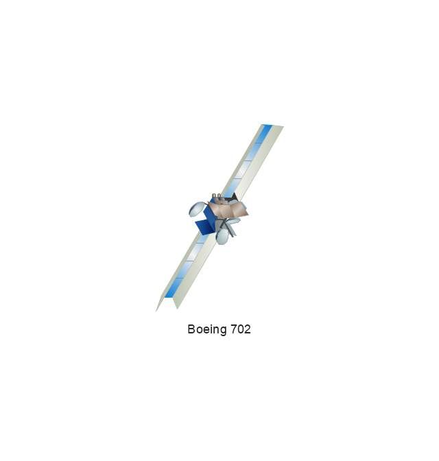
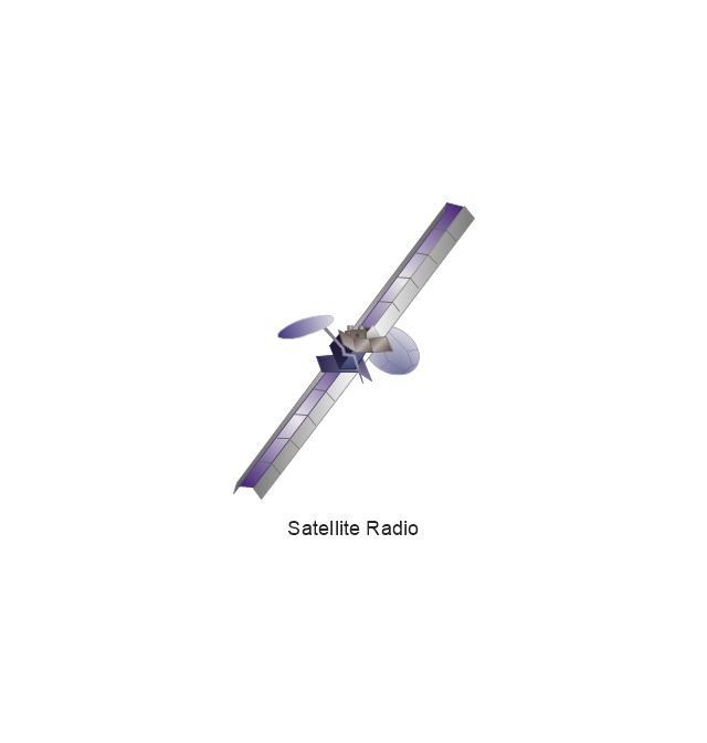
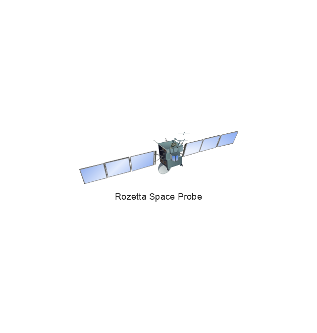
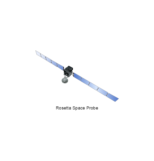
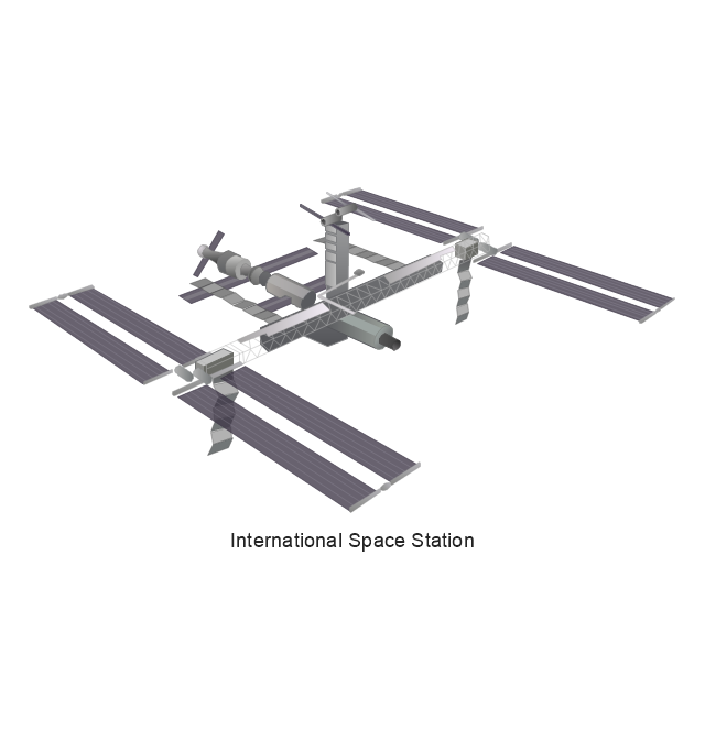
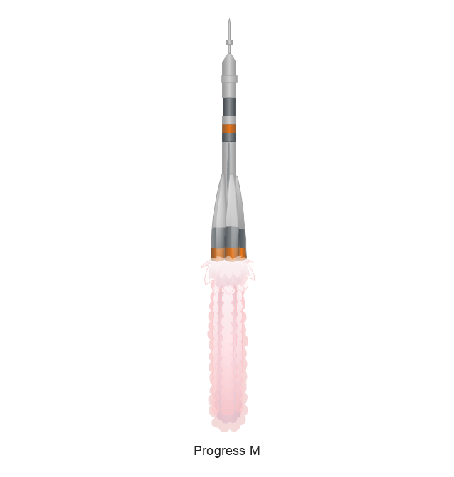
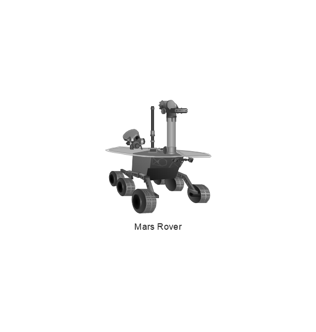
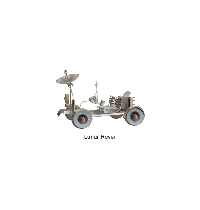
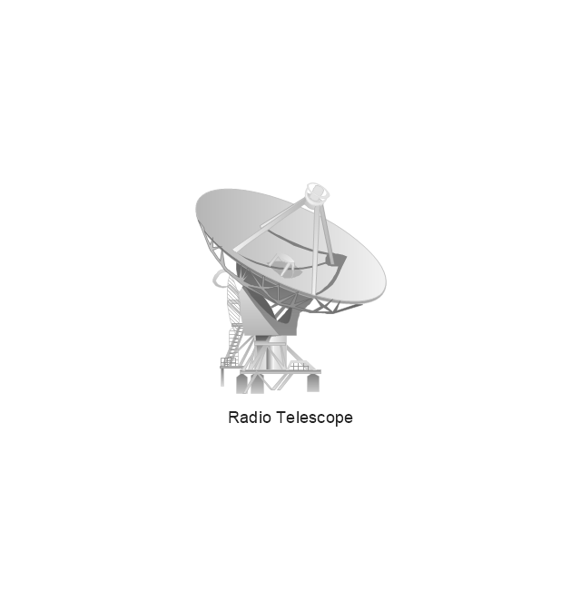
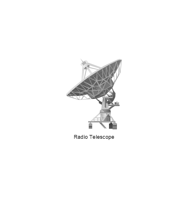
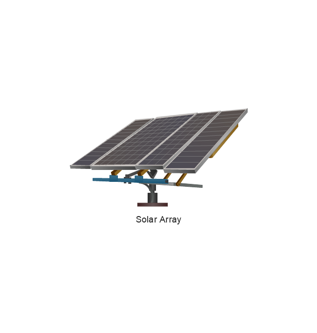
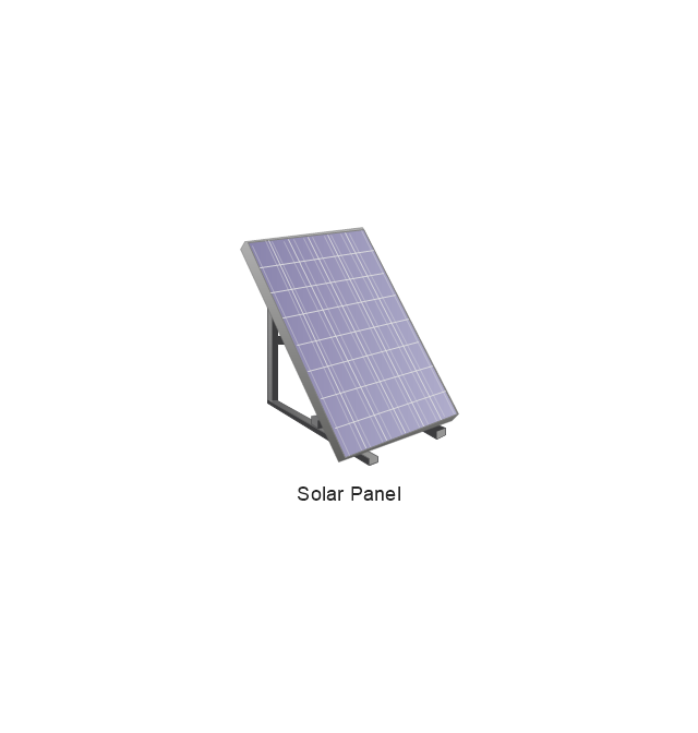
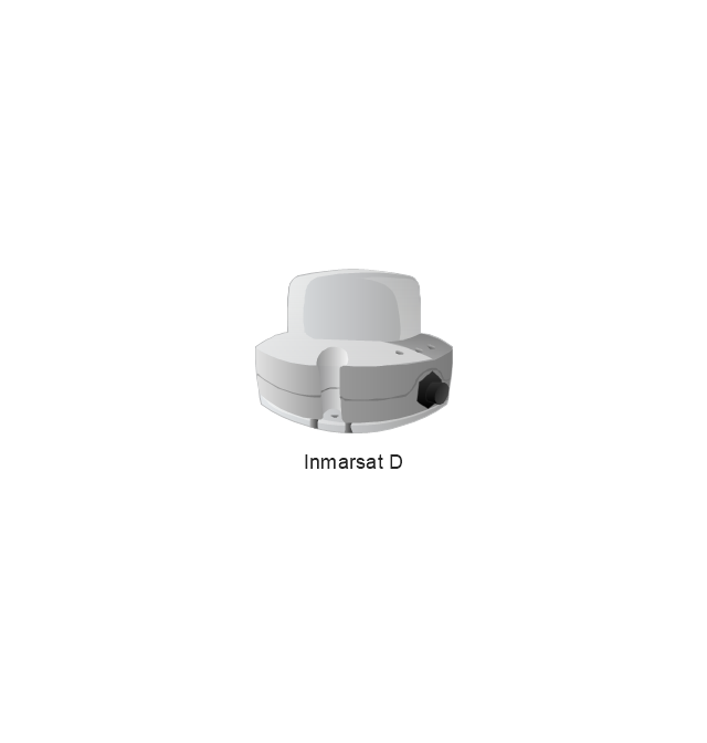
The vector stencils library "Aerospace" contains 38 clip art images for creating aerospace illustrations, presentation slides, infographics and webpages using the ConceptDraw PRO diagramming and vector drawing software.
"Aerospace describes the human effort in science, engineering and business to fly in the atmosphere of Earth (aeronautics) and surrounding space (astronautics). Aerospace organisations research, design, manufacture, operate, or maintain aircraft and/ or spacecraft. Aerospace activity is very diverse, with a multitude of commercial, industrial and military applications.
Aerospace is not the same as airspace, which is the physical air space directly above a location on the ground." [Aerospace. Wikipedia]
The vector stencils library "Aerospace" is included in the Aerospace and Transport solution from the Illustrations area of ConceptDraw Solution Park.
www.conceptdraw.com/ solution-park/ illustrations-aerospace-transport
Boeing 702
Satellite Radio
Rosetta Space Probe
Rosetta Space Probe
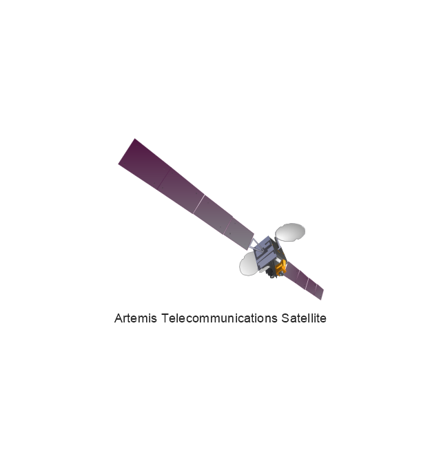
Artemis Telecommunications Satellite
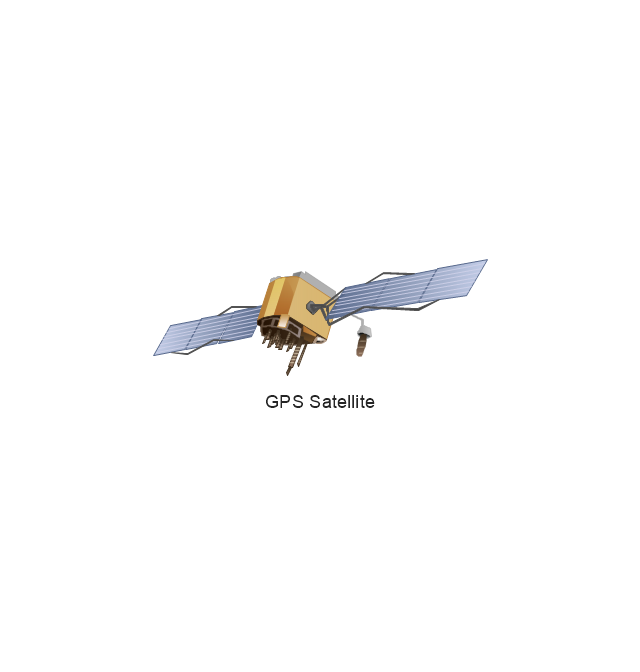
GPS Satellite
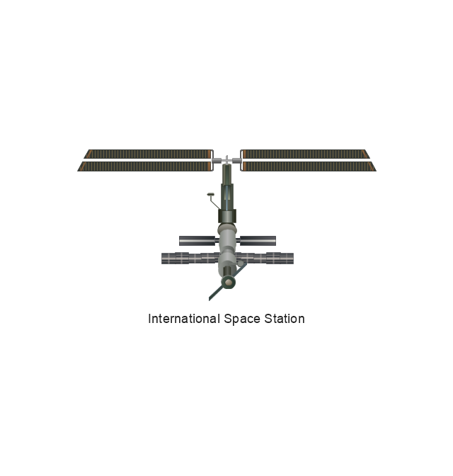
International Space Station
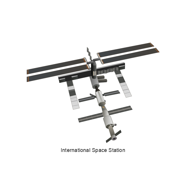
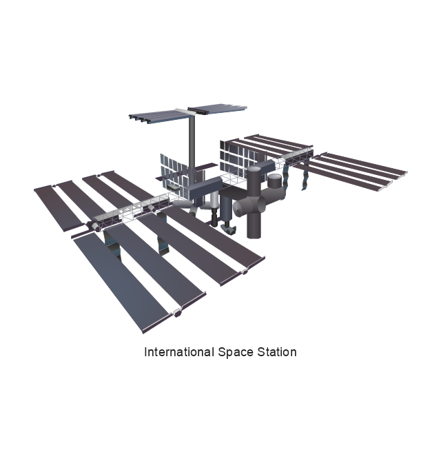
International Space Station
International Space Station
International Space Station
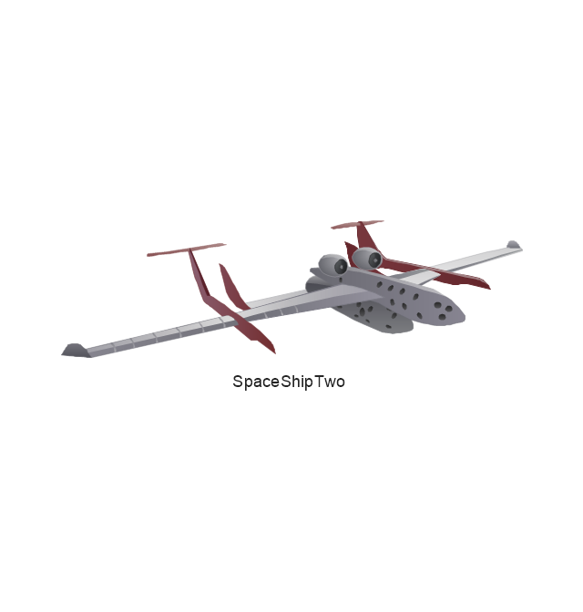
SpaceShipTwo
Shuttle Discovery

Shuttle Atlantis

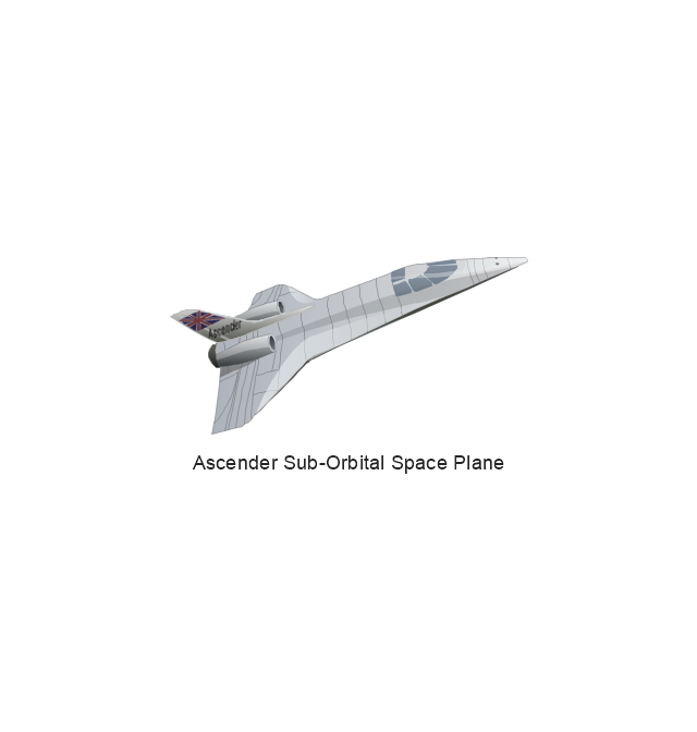
Ascender Sub-Orbital Space Plane
Progress M
Mars Rover
Lunar Rover
Radio Telescope
Radio Telescope
Solar Array
Solar Panel
Inmarsat D
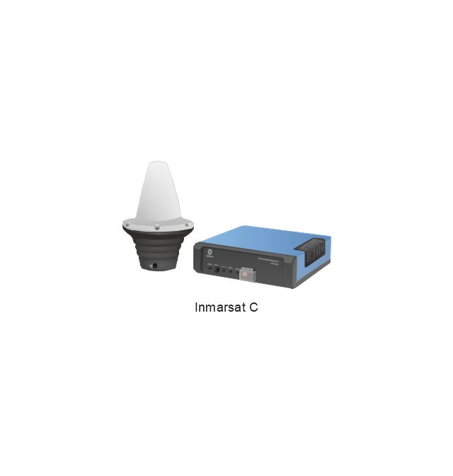
Inmarsat C
Spacesuit

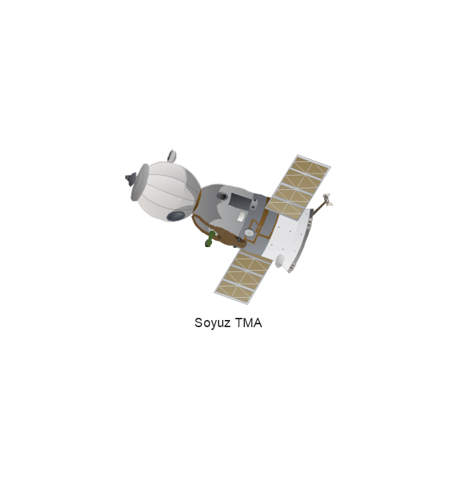
Soyuz TMA
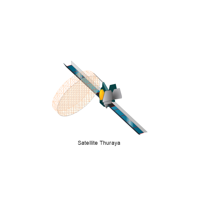
Satellite Thuraya
Tracking Headquarters
Earth

Earth

Earth

Earth

Moon
Galaxy
Galaxy
Galaxy
Astronaut/Cosmonaut

Tracking Headquarters
Night Sky

Accounting Flowchart Symbols

HelpDesk
How to Create a CCTV Diagram

The vector stenvils library "Outlets" contains 57 symbols of electrical outlets for drawing building interior design, electrical floor plans and layouts of AC power plugs and sockets.
"AC power plugs and sockets are devices that allow electrically operated equipment to be connected to the primary alternating current (AC) power supply in a building. Electrical plugs and sockets differ in voltage and current rating, shape, size and type of connectors. The types used in each country are set by national standards, some of which are listed in the IEC technical report TR 60083, Plugs and socket-outlets for domestic and similar general use standardized in member countries of IEC.
Plugs and sockets for portable appliances started becoming available in the 1880s, to replace connections to light sockets with easier to use wall-mounted outlets. A proliferation of types developed to address the issues of convenience and protection from electric shock. Today there are approximately 20 types in common use around the world, and many obsolete socket types are still found in older buildings. Co-ordination of technical standards has allowed some types of plugs to be used over wide regions to facilitate trade in electrical appliances, and for the convenience of travellers and consumers of imported electrical goods. Some multi-standard sockets allow use of several different types of plugs; improvised or unapproved adapters between incompatible sockets and plugs may not provide the full safety and performance of an approved adapter." [AC power plugs and sockets. Wikipedia]
The example "Design elements - Outlets" was created using the ConceptDraw PRO diagramming and vector drawing software extended with the Electric and Telecom Plans solution from the Building plans area of ConceptDraw Solution Park.
Electrical outlet symbols

The vector stencils library "Electrical circuits" contains 49 element symbols of electrical and electronic devices, including ignitors, starters, transmitters, circuit protectors, transducers, radio and audio equipment.
Use it for drawing electronic circuit diagrams and electrical schematics.
"An electrical network is an interconnection of electrical elements such as resistors, inductors, capacitors, voltage sources, current sources and switches. An electrical circuit is a network consisting of a closed loop, giving a return path for the current. Linear electrical networks, a special type consisting only of sources (voltage or current), linear lumped elements (resistors, capacitors, inductors), and linear distributed elements (transmission lines), have the property that signals are linearly superimposable. They are thus more easily analyzed, using powerful frequency domain methods such as Laplace transforms, to determine DC response, AC response, and transient response.
A resistive circuit is a circuit containing only resistors and ideal current and voltage sources. Analysis of resistive circuits is less complicated than analysis of circuits containing capacitors and inductors. If the sources are constant (DC) sources, the result is a DC circuit.
A network that contains active electronic components is known as an electronic circuit. Such networks are generally nonlinear and require more complex design and analysis tools." [Electrical network. Wikipedia]
The symbils example "Design elements - Electrical circuits" was drawn using the ConceptDraw PRO diagramming and vector drawing software extended with the Electrical Engineering solution from the Engineering area of ConceptDraw Solution Park.
Electrical circuit elements

Electrical Symbols — Rotating Equipment

 Electrical Engineering
This solution extends ConceptDraw DIAGRAM.9.5 (or later) with electrical engineering samples, electrical schematic symbols, electrical diagram symbols, templates and libraries of design elements, to help you design electrical schematics, digital and analog
The vector stencils library "Application" contains 40 icons of software applications.
Use it to design your computer and telecom illustrations and infographics with ConceptDraw PRO diagramming and vector drawing software.
The vector stencils library "Application" is included in the Computers and Communications solution from the Illustration area of ConceptDraw Solution Park.
Use it to design your computer and telecom illustrations and infographics with ConceptDraw PRO diagramming and vector drawing software.
The vector stencils library "Application" is included in the Computers and Communications solution from the Illustration area of ConceptDraw Solution Park.
Book

Lecture book

E-learning

Education

Graduate

A plus

Student

Position holder

Achievement

Diamond

Present

Balance scale

Law

Atom

Formula
Chemistry

Research

Measuring

Plan

Calendar

Notice pin

Appointment

Tea cup

Journal

Archive

Calculator
Text format

Graphic editor

Vector graphics

Digital art board

Creative

Design

Adaptive

ECG
Forecast book

Presentation

Shopping basket

Platform truck

Printer

Air conditioner
Design Element: Active Directory for Network Diagrams


Circles Venn Diagram

3 Circle Venn. Venn Diagram Example

Cisco Icons

- Design elements - Transformers and windings | Transformers and ...
- Electrical Symbols — Electrical Circuits | Design elements ...
- Electrical Symbols — Power Sources | Electrical Symbols ...
- Electrical Symbols, Electrical Diagram Symbols | Electrical Symbols ...
- Wire Joint Symbol
- Electrical Symbols — Electrical Circuits | Electrical circuits - Vector ...
- Electrical circuits - Vector stencils library | Design elements ...
- Design elements - Electrical circuits | Electrical circuits - Vector ...
- Classroom lighting - Reflected ceiling plan | Reflected ceiling plan ...
- Power socket outlet layout | How To use House Electrical Plan ...
- Power socket outlet layout | Plant Layout Plans | Cafe electrical floor ...
- Wiring Of A Two Bedroom Flat And To Wire It
- Electrical Drawing Software and Electrical Symbols | How To use ...
- Accounting Flowchart Symbols | Wiring Diagrams with ConceptDraw ...
- Design elements - Outlets | Design elements - Terminals and ...
- Lighting and switch layout | Design elements - Outlets | Electrical ...
- Electrical Symbols — Power Sources | Design elements ...
- Cafe electrical floor plan | Design elements - Qualifying | Design ...
- Design elements - Transformers and windings | Electrical Symbols ...
- Electrical Symbols — IGFET | Electrical Symbols — MOSFET ...