Baseball Diagram — Baseball Field — Corner View — Sample

"Baseball is played between two teams with nine players in the field on each team. On a baseball field, the game is under authority of several umpires. There are usually four umpires in major league games; up to six (and as few as one) may officiate depending on the league and the importance of the game. There are four bases. Numbered counterclockwise, first, second and third bases are cushions (sometimes informally referred to as bags) shaped as 15 in (38 cm) squares which are raised a short distance above the ground; together with home plate, the fourth "base," they form a square with sides of 90 ft (27.4 m) called the diamond. Home base (usually called home plate) is a pentagonal rubber slab 17 in (43.2 cm) wide. The playing field is divided into three main sections:
(1) The infield, containing the four bases, is for general defensive purposes bounded by the foul lines and within the grass line (see figure).
(2) The outfield is the grassed area beyond the infield grass line between the foul lines, and bounded by a wall or fence.
(3) Foul territory is the entire area outside the foul lines.
The pitcher's mound is located in the center of the infield. It is an 18 ft (5.5 m) diameter mound of dirt no higher than 10 in (25.4 cm). Near the center of the mound is the pitching rubber, a rubber slab positioned 60 ft 6 in (18.4 m) from home plate. The pitcher must have one foot on the rubber at the start of every pitch to a batter, but the pitcher may leave the mound area once the ball is released." [Baseball rules. Wikipedia]
The baseball positions diagram example "Corner view baseball field" was created using the ConceptDraw PRO diagramming and vector drawing software extended with the Baseball solution from the Sport area of ConceptDraw Solution Park.
Baseball positions diagram

Design a Soccer (Football) Field
 Field *")
Baseball Diagram – Colored Baseball Field

This sport field plan sample was designed on the base of the Wikipedia file: VolleyballCourt.svg. [en.wikipedia.org/ wiki/ File:VolleyballCourt.svg]
This file is licensed under the Creative Commons Attribution-Share Alike 3.0 Unported license. [creativecommons.org/ licenses/ by-sa/ 3.0/ deed.en]
"Volleyball is a team sport in which two teams of six players are separated by a net. Each team tries to score points by grounding a ball on the other team's court under organized rules. It has been a part of the official program of the Summer Olympic Games since 1964. ...
The court dimensions.
A volleyball court is 18 m (59 ft) long and 9 m (29.5 ft) wide, divided into 9 m × 9 m halves by a one-meter (40-inch) wide net. The top of the net is 2.43 m (8 ft 0 in) above the center of the court for men's competition, and 2.24 m (7 ft 4 in) for women's competition, varied for veterans and junior competitions.
The minimum height clearance for indoor volleyball courts is 7 m (23 ft), although a clearance of 8 m (26 ft) is recommended.
A line 3 m (9.84 ft) from and parallel to the net is considered the "attack line". This "3 meter" (or "10-foot") line divides the court into "back row" and "front row" areas (also back court and front court). These are in turn divided into 3 areas each: these are numbered as follows, starting from area "1", which is the position of the serving player.
After a team gains the serve (also known as siding out), its members must rotate in a clockwise direction, with the player previously in area "2" moving to area "1" and so on, with the player from area "1" moving to area "6".
The team courts are surrounded by an area called the free zone which is a minimum of 3 meters wide and which the players may enter and play within after the service of the ball. All lines denoting the boundaries of the team court and the attack zone are drawn or painted within the dimensions of the area and are therefore a part of the court or zone. If a ball comes in contact with the line, the ball is considered to be "in". An antenna is placed on each side of the net perpendicular to the sideline and is a vertical extension of the side boundary of the court. A ball passing over the net must pass completely between the antennae (or their theoretical extensions to the ceiling) without contacting them." [Volleyball. Wikipedia]
The sport field plan example "Volleyball court dimensions" was created using the ConceptDraw PRO diagramming and vector drawing software extended with the Sport Field Plans solution from the Building Plans area of ConceptDraw Solution Park.
Sport field plan

Defensive Formation – 4-3 Defense Diagram

Defensive Strategy Diagram – 46 Defence

"Markings.
Lines.
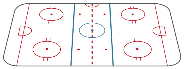
The centre line divides the ice in half crosswise. It is used to judge icing, meaning that if a team sends the puck across the centre line (red line), blue line and then across the goal line (that is to say, shoots or dumps the puck past the goal line from behind their own side of the centre line) it is said to be icing. ...
Faceoff spots and circles.
There are 9 faceoff spots on a hockey rink. Most faceoffs take place at these spots. There are two spots in each end zone, two at each end of the neutral zone, and one in the centre of the rink.
There are faceoff circles around the centre ice and end zone faceoff spots. There are hash marks painted on the ice near the end zone faceoff spots. The circles and hash marks show where players may legally position themselves during a faceoff or in game play. ...
Spot and circle dimensions.
Both the center faceoff spot and center faceoff circle are blue. The spot is a solid blue circle 12 inches (30 cm) in diameter. Within the spot is a center, a circle 30 feet (9.1 m) in diameter, painted with a blue line 2 inches (5.1 cm) in width.
All of the other faceoff spots have outlines 2 inches (5.1 cm) thick, forming a circle 2 feet (0.61 m) in diameter measured from the outsides of the outlines, and are filled in with red in all areas except for the 3 inches (7.6 cm) space from the tops and bottoms of the circles, measured from the insides of the outline. ...
Goal posts and nets.
At each end of the ice, there is a goal consisting of a metal goal frame and cloth net in which each team must place the puck to earn points. According to NHL and IIHF rules, the entire puck must cross the entire goal line in order to be counted as a goal. ...
Goal area.
The crease is a special area of the ice designed to allow the goaltender to perform without interference. In most leagues, goals are disallowed if an attacking player enters the goal crease with a stick, skate, or any body part before the puck. For the purposes of this rule, the crease extends vertically from the painted lines to the top of the goal frame. ...
Goaltender trapezoid.
During the 2004-05 American Hockey League (AHL) season, an experimental rule was implemented for the first seven weeks of the season, instituting a goaltender trap zone, more commonly called the trapezoid in reference to its shape. Under the rule, it is prohibited for the goaltender to handle the puck anywhere behind the goal line that is not within the trapezoidal area. If they do so they are assessed a minor penalty for delay of game. ...
Referee's crease.
The referee's crease is a semicircle ten feet in radius in front of the scorekeepers bench." [Ice hockey rink. Wikipedia]
The diagram template "Ice hockey rink view from long side" for the ConceptDraw PRO diagramming and vector drawing software is included in the Hockey solution from the Sport area of ConceptDraw Solution Park.
Lines.
The centre line divides the ice in half crosswise. It is used to judge icing, meaning that if a team sends the puck across the centre line (red line), blue line and then across the goal line (that is to say, shoots or dumps the puck past the goal line from behind their own side of the centre line) it is said to be icing. ...
Faceoff spots and circles.
There are 9 faceoff spots on a hockey rink. Most faceoffs take place at these spots. There are two spots in each end zone, two at each end of the neutral zone, and one in the centre of the rink.
There are faceoff circles around the centre ice and end zone faceoff spots. There are hash marks painted on the ice near the end zone faceoff spots. The circles and hash marks show where players may legally position themselves during a faceoff or in game play. ...
Spot and circle dimensions.
Both the center faceoff spot and center faceoff circle are blue. The spot is a solid blue circle 12 inches (30 cm) in diameter. Within the spot is a center, a circle 30 feet (9.1 m) in diameter, painted with a blue line 2 inches (5.1 cm) in width.
All of the other faceoff spots have outlines 2 inches (5.1 cm) thick, forming a circle 2 feet (0.61 m) in diameter measured from the outsides of the outlines, and are filled in with red in all areas except for the 3 inches (7.6 cm) space from the tops and bottoms of the circles, measured from the insides of the outline. ...
Goal posts and nets.
At each end of the ice, there is a goal consisting of a metal goal frame and cloth net in which each team must place the puck to earn points. According to NHL and IIHF rules, the entire puck must cross the entire goal line in order to be counted as a goal. ...
Goal area.
The crease is a special area of the ice designed to allow the goaltender to perform without interference. In most leagues, goals are disallowed if an attacking player enters the goal crease with a stick, skate, or any body part before the puck. For the purposes of this rule, the crease extends vertically from the painted lines to the top of the goal frame. ...
Goaltender trapezoid.
During the 2004-05 American Hockey League (AHL) season, an experimental rule was implemented for the first seven weeks of the season, instituting a goaltender trap zone, more commonly called the trapezoid in reference to its shape. Under the rule, it is prohibited for the goaltender to handle the puck anywhere behind the goal line that is not within the trapezoidal area. If they do so they are assessed a minor penalty for delay of game. ...
Referee's crease.
The referee's crease is a semicircle ten feet in radius in front of the scorekeepers bench." [Ice hockey rink. Wikipedia]
The diagram template "Ice hockey rink view from long side" for the ConceptDraw PRO diagramming and vector drawing software is included in the Hockey solution from the Sport area of ConceptDraw Solution Park.
Ice hockey rink diagram template
 Baseball
The Baseball Solution extends ConceptDraw DIAGRAM.5 (or later) software with samples, templates, and libraries of vector objects for drawing baseball diagrams, plays, and illustrations. It can be used to make professional looking documents, presentations,
Ice Hockey Rink Diagram

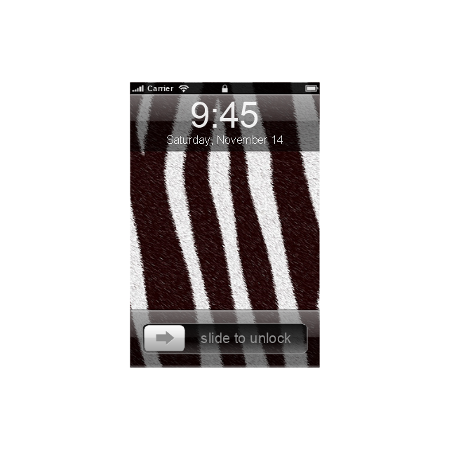
The vector stencils library "iPhone interface" contains 119 iPhone UI design elements.
Use it for development of graphic user interface (GUI) for iPhone software applications in the ConceptDraw PRO diagramming and vector drawing software extended with the Graphic User Interface solution from the Software Development area of ConceptDraw Solution Park.
Use it for development of graphic user interface (GUI) for iPhone software applications in the ConceptDraw PRO diagramming and vector drawing software extended with the Graphic User Interface solution from the Software Development area of ConceptDraw Solution Park.
iPhone case
iPhone case, horizontal
Display
Screen

Home screen
Keypad control

Status bar
Navigation bar

Navigation bar with buttons

Navigation bar with controls
Navigation bar with controls

Navigation bar with buttons, horizontal

Navigation bar with controls, horizontal
Modal view
Search bar
Text field 1

Text field 2

Text field, varying

Table row
Table view row

Table view (simple list)
-iphone-interface---vector-stencils-library.png--diagram-flowchart-example.png)
Table view (with header)
-iphone-interface---vector-stencils-library.png--diagram-flowchart-example.png)
Action list
Control button
Navigational control button

Add button
Navigation toolbar

Tab bar

Action sheet

Choice button

Rounded rectangle button
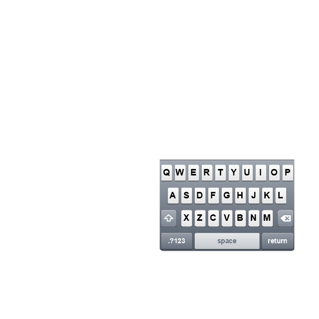
Keyboard control
Keyboard literal button
Keyboard button, pressed
Keyboard label button

Selection frame 1

Selection frame 2

Loupe

Message box 1
Message box 2

Progress view

Progress view

Progress view

Player control

Label button

Back button

Forward button

Option button
Checkbox

Radio button

Alert

Two-button alert
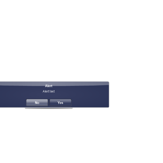
Two-button alert (v 3.0)
-iphone-interface---vector-stencils-library.png--diagram-flowchart-example.png)
Up-Down control

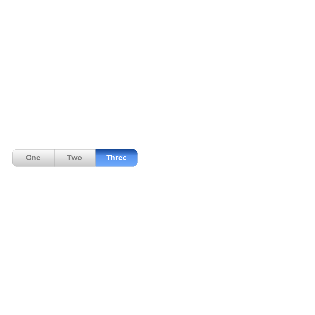
Segmented control

Segmented control

Segmented control
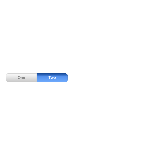
Segmented control
Pop-up menu button

Popup menu

Clock, white

Clock, black

Clock application table

Date and time picker (1/2 parts)
-iphone-interface---vector-stencils-library.png--diagram-flowchart-example.png)
Date and time picker (3 parts)
-iphone-interface---vector-stencils-library.png--diagram-flowchart-example.png)
Date and time picker (4 parts)
-iphone-interface---vector-stencils-library.png--diagram-flowchart-example.png)
Date and time picker (v 3.0)
-iphone-interface---vector-stencils-library.png--diagram-flowchart-example.png)
Switch control

System button

Reply button

Organize button

Remove button

Refresh button

Play button

FastForward button

Pause button

Rewind button

Backward icon
Forward icon
Share button

Camera button

Compose button

Bookmarks button

Search button

Add button

Trash button

Bookmarks tab icon
Contacts tab icon
Downloads tab icon
Favorites tab icon
Featured tab icon
History tab icon
MostRecent tab icon
MostViewed tab icon
Search tab icon
More tab icon
SMS tab icon
Mail tab icon
Charts tab icon
World clock tab icon
Alarm tab icon
Stopwatch tab icon
Timer tab icon
Badge
Delete button control

Checkmark

Delete button

Insert

Disclosure indicator

Clear button

Bookmarks badge
Badge with varying width 1
Badge with varying width 2
Badge with varying width 3
Activity indicator

Network activity indicator

Page control

Search badge
Slider

Basketball Plays Software
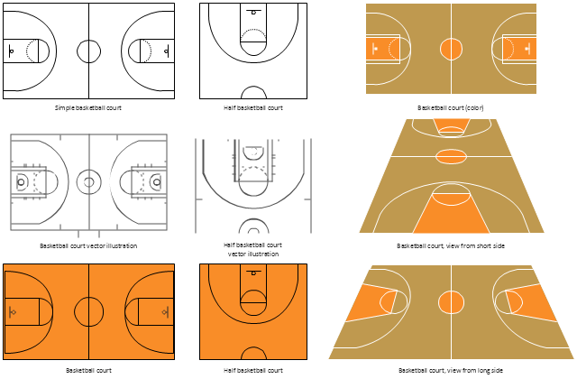
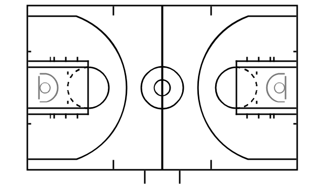
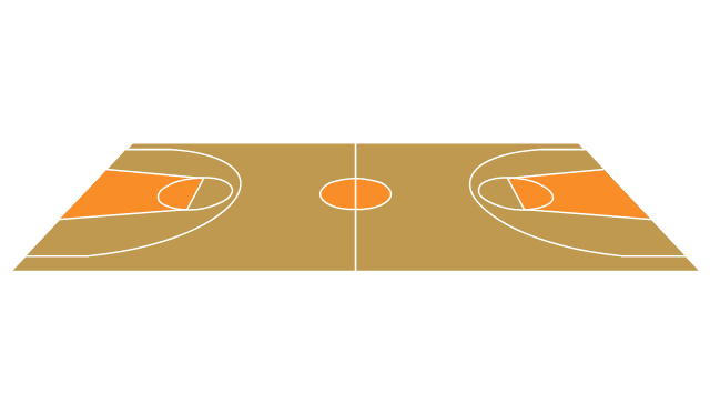
The vector stencils library "Basketball courts" contains 8 templates of basketball court diagrams.
"In basketball, the basketball court is the playing surface, consisting of a rectangular floor with tiles at either end. In professional or organized basketball, especially when played indoors, it is usually made out of a wood, often maple, and highly polished. Outdoor surfaces are generally made from standard paving materials such as concrete or asphalt (i.e. blacktop/ tarmac)." [Basketball court. Wikipedia]
The example "Design elements - Basketball courts" was created using the ConceptDraw PRO diagramming and vector drawing software extended with the Basketball solution from the Sport area of ConceptDraw Solution Park.
www.conceptdraw.com/ solution-park/ sport-basketball
Basketball court templates
This pitch plan sample was designed on the base of the Wikipedia file: Comparison sport playing areas.svg.
[en.wikipedia.org/ wiki/ File:Comparison_ sport_ playing_ areas.svg]
This file is licensed under the Creative Commons Attribution-Share Alike 3.0 Unported license. [creativecommons.org/ licenses/ by-sa/ 3.0/ deed.en]
"A pitch is an outdoor playing area for various sports. The term is used in British and Australian English; the comparable term in American English is playing field. In most sports, the official technical term is field of play, although this is not regularly used by those outside of refereeing/ umpiring circles.
In the sport of cricket, the cricket pitch refers not to the entire field of play, but to the section of the field on which batting and bowling take place in the centre of the field. The pitch is prepared differently to the rest of the field, to provide a harder surface for bowling.
A pitch is often a regulation space, as in an association football pitch." [Pitch (sports field). Wikipedia]
The pitch plan example "Sport fields comparison" was created using the ConceptDraw PRO diagramming and vector drawing software extended with the Sport Field Plans solution from the Building Plans area of ConceptDraw Solution Park.
Pitch plans

Basketball Court Dimensions

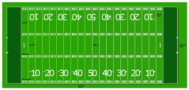
"Football games are played on a rectangular field that measures 120 yards (110 m) long and 53.33 yards (48.76 m) wide. Lines marked along the ends and sides of the field are known respectively as the end lines and side lines, and goal lines are marked 9 yards (8.2 m) outward from each end line. Weighted pylons are placed on the inside corner of the intersections of the goal lines and end lines.
White markings on the field identify the distance from the end zone. Inbound lines, or hash marks, are short parallel lines that mark off 1 yard (0.91 m) increments. Yard lines, which run the width of the field, are marked every 5 yards (4.6 m). A line one yard wide is placed at each end of the field. This line is marked at the center of the two-yard line in professional play and at the three-yard line in college play. Numerals that display the yard lines in multiples of ten are placed along both sides of the field.
Goalposts are at the center of the plane of each of the two end lines. The crossbar of these posts is ten feet (3 meters) above the ground, with vertical uprights at the end of the crossbar 18 feet 6 inches (6 m) apart for professional and collegiate play and 23 feet 4 inches (7 m) apart for high school play. The uprights extend vertically 10 yards on professional fields, a minimum of 10 yards on college fields, and a minimum of ten feet on high school fields. Goal posts are padded at the base, and orange ribbons are normally placed at the tip of each upright." [American football. Wikipedia]
The diagram example "Horizontal colored football field" was created using the ConceptDraw PRO diagramming and vector drawing software extended with the Football solution from the Sport area of ConceptDraw Solution Park.
American football field diagram
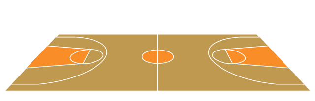
The vector stencils library "Basketball courts" contains 8 templates of basketball court diagrams.
Use it to draw basketball positions diagrams in the ConceptDraw PRO diagramming and vector drawing software extended with the Basketball solution from the Sport area of ConceptDraw Solution Park.
www.conceptdraw.com/ solution-park/ sport-basketball
Use it to draw basketball positions diagrams in the ConceptDraw PRO diagramming and vector drawing software extended with the Basketball solution from the Sport area of ConceptDraw Solution Park.
www.conceptdraw.com/ solution-park/ sport-basketball
Basketball court vector illustration
Basketball court
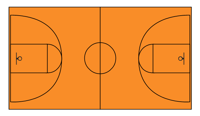
Basketball court (color)
-basketball-courts---vector-stencils-library.png--diagram-flowchart-example.png)
Simple basketball court
Basketball court, view from long side
Basketball court, view from short side
Half basketball court
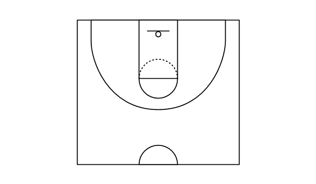
Half basketball court vector illustration

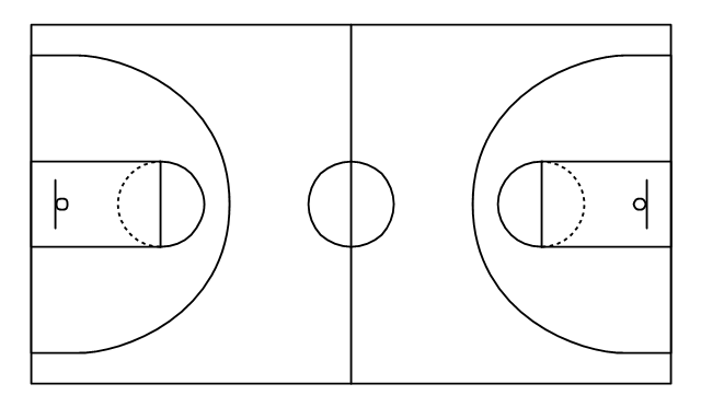
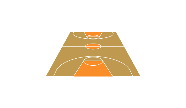
Use this basketball court template to draw basketball positions diagrams.
The template "Basketball court view from long side" for the ConceptDraw PRO diagramming and vector drawing software is included in the Basketball solution from the Sport area of ConceptDraw Solution Park.
www.conceptdraw.com/ solution-park/ sport-basketball
The template "Basketball court view from long side" for the ConceptDraw PRO diagramming and vector drawing software is included in the Basketball solution from the Sport area of ConceptDraw Solution Park.
www.conceptdraw.com/ solution-park/ sport-basketball
Basketball court template
- Draw A Well Labelled Football Field With Position Of Players
- Basketball Court Diagram and Basketball Positions | Basketball ...
- Diagram Of A Hockey Pitch And Labelled
- Soccer (Football) Positions | Soccer (Football) Formation | Offensive ...
- Volleyball court dimensions | Design elements - Soccer silhouettes ...
- Fully Labelled Football Pitch With Players On Their Wings
- Basketball Court Diagram and Basketball Positions | Soccer ...
- Basketball Court Diagram and Basketball Positions | Soccer ...
- Soccer (Football) Positions | Soccer (Football) Offside | Offensive ...
- Football Field With Position Labelling
- Soccer (Football) Formation | Create Soccer (Football) Positions ...
- Soccer (Football) Formation | Design a Soccer (Football) Field ...
- Design a Soccer (Football) Field | Soccer (Football) Dimensions ...
- Soccer (Football) Positions | Baseball Diagram – Basic Bunt ...
- Soccer (Football) Field Templates | Design a Soccer (Football) Field ...
- Basketball Court Diagram and Basketball Positions | Ice Hockey ...
- Draw And Label A Soccer Pitch
- Baseball Diagram – Colored Baseball Field | Baseball Field Sample ...
- Images Of A Football Field Numbers With Their Positions Of Players
- Soccer (Football) Positions | Soccer (Football) Field Templates ...