Electrical Symbols — Rotating Equipment

Electrical Symbols — Transformers and Windings
Electrical Symbols, Electrical Diagram Symbols

Electrical Symbols — Qualifying

Electrical Drawing Software and Electrical Symbols

The vector stencils lybrary "Rotating equipment" contains 55 symbols of rotating equipment: converters, generators, motors, rotating machines, and their parts and labels.
Use to design systems containing rotating electrical equipment (i.e., motors), armatures, brushes, and related mechanical devices ( brakes, gearing, clutches, interlocks) in the ConceptDraw PRO diagramming and vector drawing software extended with the Electrical Engineering solution from the Engineering area of ConceptDraw Solution Park.
www.conceptdraw.com/ solution-park/ engineering-electrical
Permanent magnet

Gearing
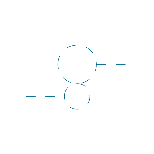
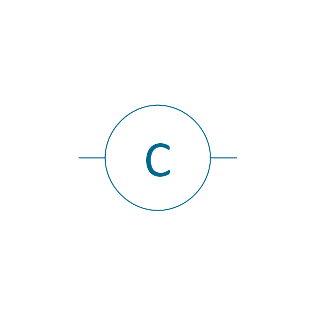
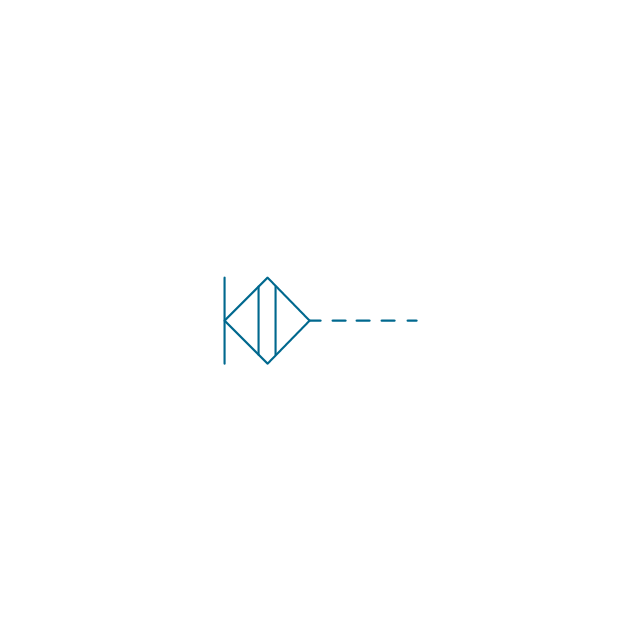
Synchronous converter
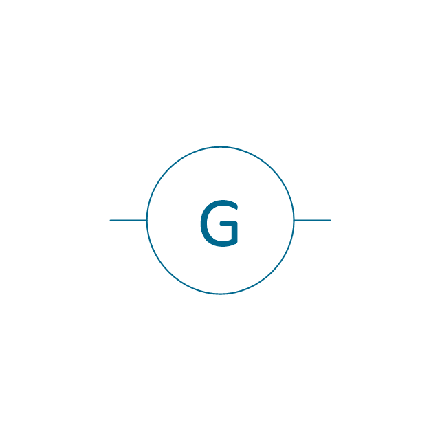
Generator
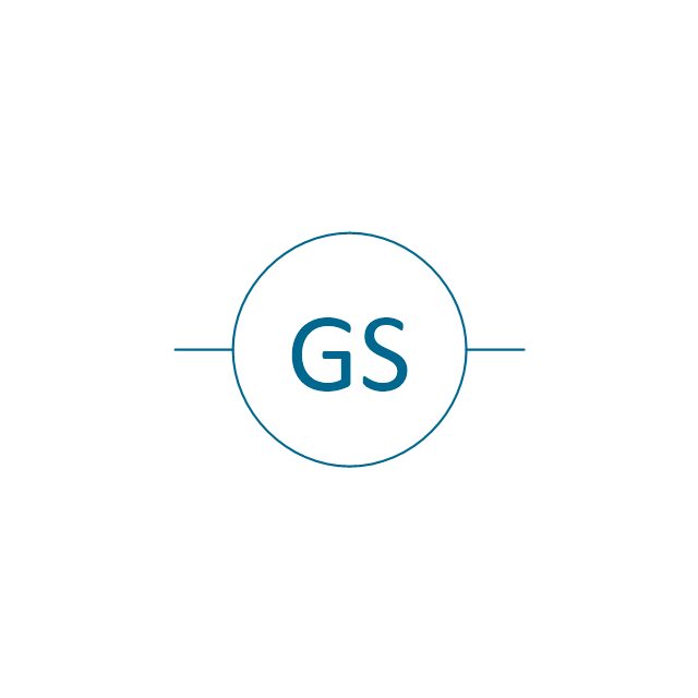
Synchronous generator
Motor

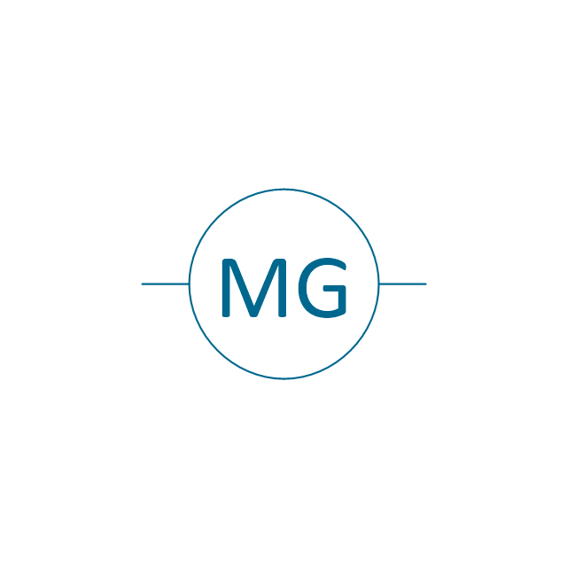
Motor generator
Synchronous motor

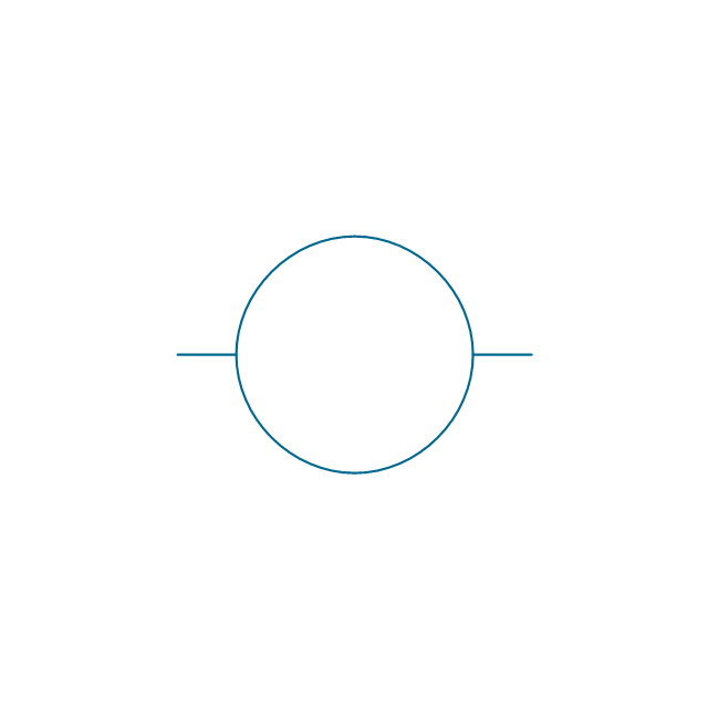
Rotating machine
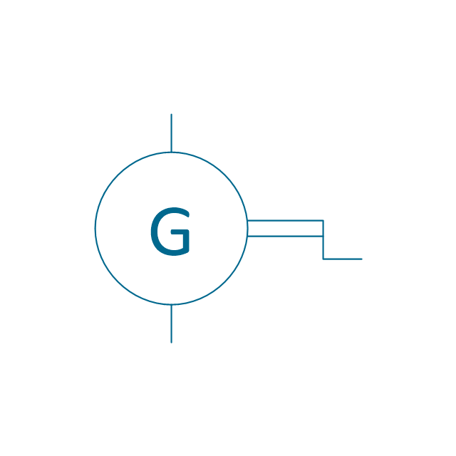
Hand generator
1 brush

2 brushes

Field, commutating or compensating

Field, series

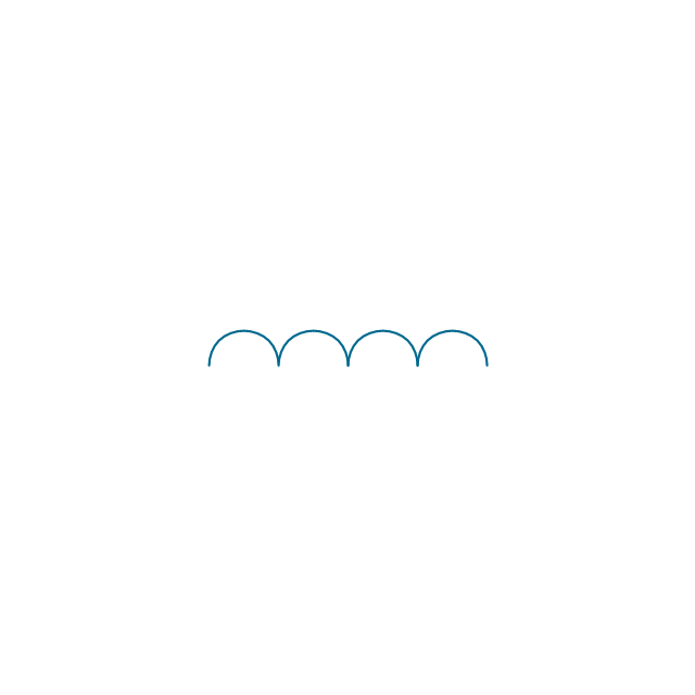
Field, shunt or separate
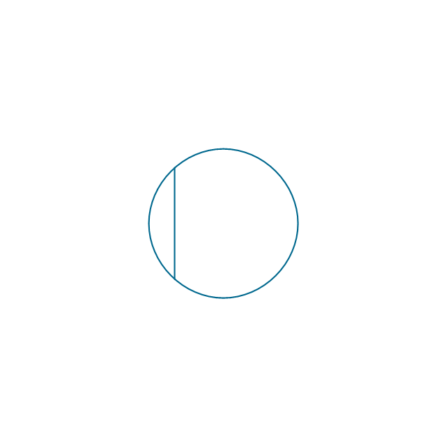
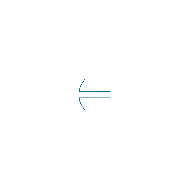
Winding connection, 1 phase
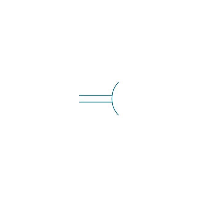
Winding connection, 2 phase

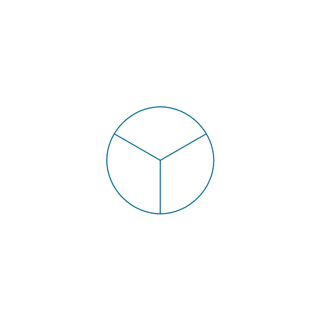
Winding connection, 3 phase wye
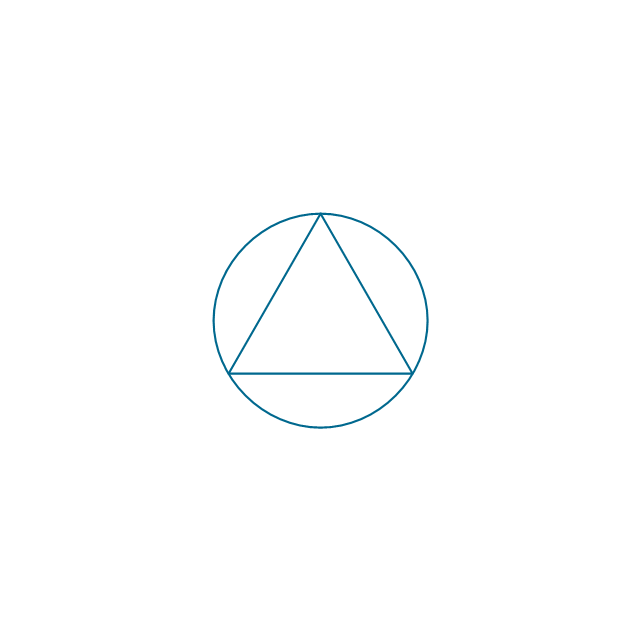
Winding connection, 3 phase delta
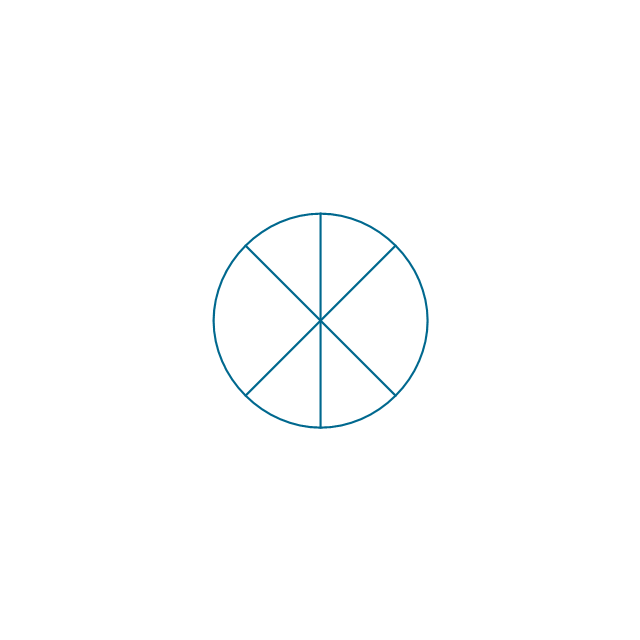
Winding connection, 6 phase diametrical
Winding connection, 6 phase double delta

Synchro general
Synchro, control transformer
Synchro, differential receiver
Synchro, resolver

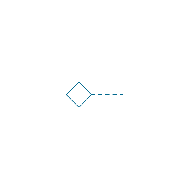
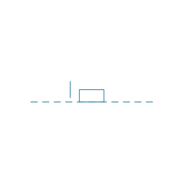
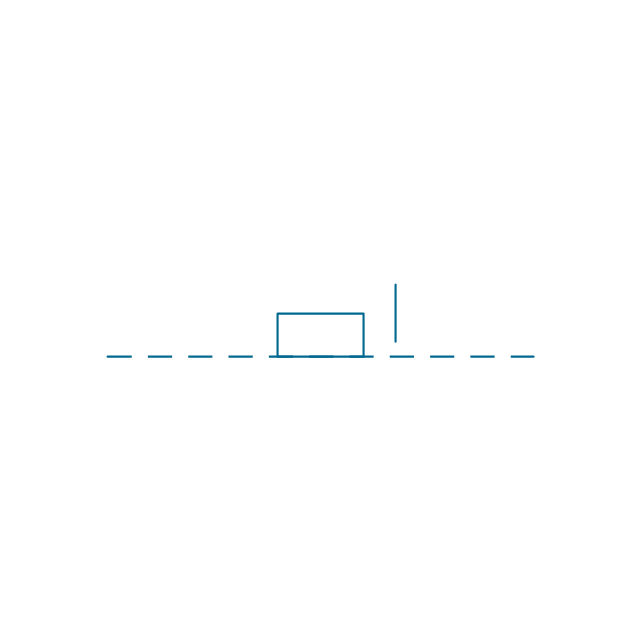
Brake
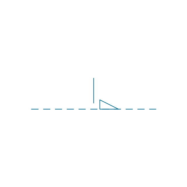
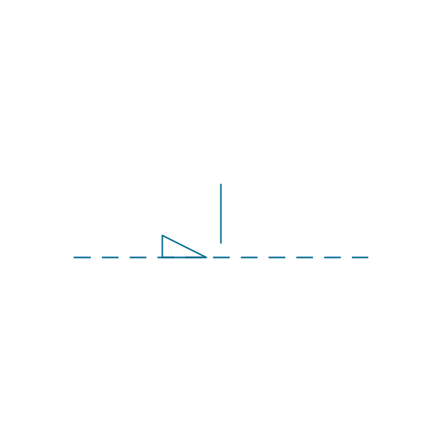
Rotation 2

Rotation

Clutch, engaged
Clutch, disengaged
Clutch, engaged 2
Clutch, disengaged 2
Delayed action
Delayed action 2
Manual control, general
Manual control, pushing
Manual control, push/pull
Manual control, pulling
Manual control, turning
Manual control, emergency switch
Manual control, proximity effect

Manual control, touching
Manual control, remote handle
Manual control, handwheel

Manual control, key

Manual control, roller

Manual control, crunk
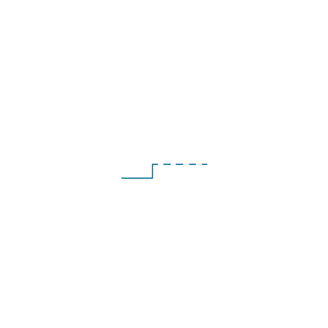
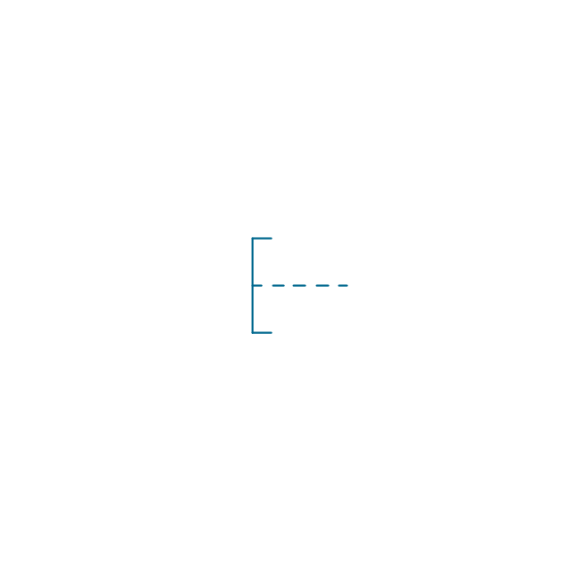
Blocking device
Blocking device 2
Blocking device 3
Latching device, engaged
Latching device, disengaged
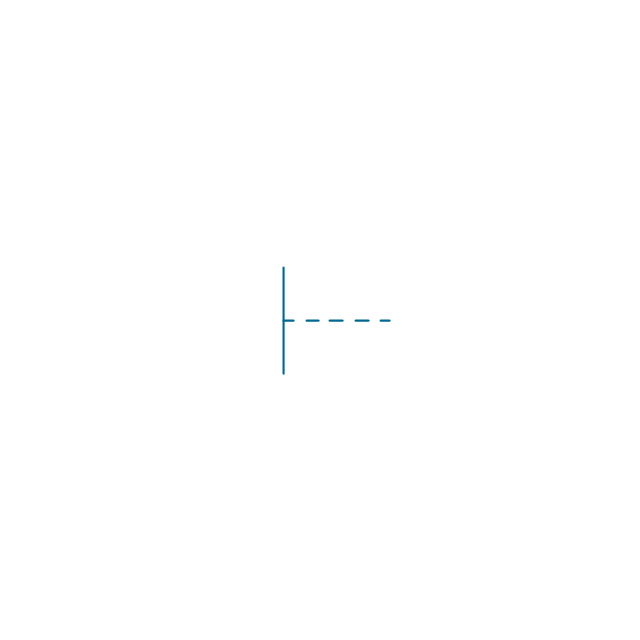
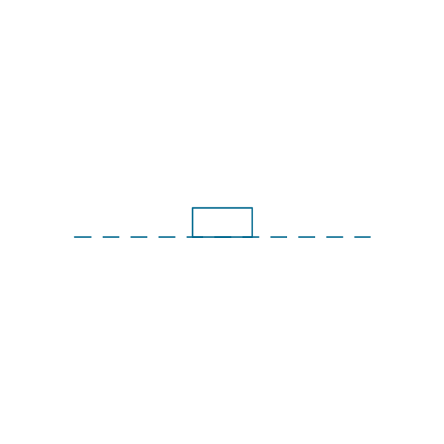
Mechanical interlock
Automatic return
Detent
Electrical Symbols — Composite Assemblies

Electrical Symbols — Inductors

Electrical Symbols — Thermo

Electrical Symbols — Stations

- Single Phase Motor Winding Diagram
- Single Phase Electric Motor Winding Diagram Software
- Single Phase Wiring Diagram For House
- Fan Motor Winding Diagram
- Single Phase Electrical Motor Winding Diagram Download
- Electrical Symbols, Electrical Diagram Symbols | Exhaust Motors ...
- Table Fan Single Phase Pole Winding Diagram Connection
- Singlephasemotor Winding Diagrams
- Ceiling Fans Winding Diagrams
- Motor Winding Diagram Software