Line Graph
Looking for the line graph examples you can simply go to the Line Graphs solution of ConceptDraw STORE to get those which were previously created especially for the ConceptDraw DIAGRAM users in order to simplify their work of making such charts.
The previously Line Graphs solution contains five stencil objects that are the templates of line graphs named as “Line Graph — Relative Price Changes”, “Line Graph — Number of Airlines Departures in the Given Years”, “Line Graph — France Export of Goods and Services”, “Line Graph — Spets Walked in a Week” and “Line Graph — Percent of Students a 36 on ACT”.
You can also find some more samples of line graphs within the previously mentioned product of CS Odessa — ConceptDraw STORE. They are: “Line Graph — Circuit Efficiency Erlang B”, “Line Graph — 1918 Spanish Flu Waves”, “Veteran Point in Time Counts, 2009—2012” and “Wait Time for Treatment in Hospital Emergency Department”.
The line graph of an undirected graph G in the mathematical discipline of graph theory is another graph L(G) used for representing different adjacencies between all the edges of G. The term “line graph” is known to be originally coming from a paper by Harary & Norman, although both Whitney and Krausz used this construction before.
Other terms that are used for the line graph are known to be including the derivative, the covering graph, the conjugate, the edge-to-vertex dual, the representative graph, the edge graph, the ϑ-obrazom, the interchange graph, the derived graph and the adjoint graph.
Hassler Whitney was the one who proved that with only one exceptional case the structure of a so-called connected graph G can be recovered from its line graph completely. A lot of other properties of the line graphs are known to be following by translating the properties of the underlying graph from vertices into edges. Thus, by Whitney's theorem, the very same translation can also be done in any other direction.
All the line graphs are known to be claw-free. All the line graphs of bipartite graphs are known to be perfect. Any line graph can be characterized by nine forbidden subgraphs, being recognized in the linear time. There are many generalizations of the line graphs that have also been studied, including the line graphs of multigraphs, the line graphs of line graphs, the line graphs of weighted graphs and the line graphs of hypergraphs.
As with claw-free graphs, every connected line graph L(G) with an even number of the edges has a perfect matching. This means that in case the underlying graph G has an even number of edges, then its edges can be partitioned into the two-edge paths. All the line graphs of trees are known to be exactly the claw-free block graphs. The mentioned graphs have been used for solving a problem in an extremal graph theory.
Constructing a graph with a given number of vertices and edges whose largest tree induced as a subgraph is as small as possible. Although the line graph of a bipartite graph is perfect, it still should not be bipartite. The line graphs of the bipartite graphs form one of the key building blocks of the perfect graphs that are used in the proof of the strong perfect graph theorem.
The mentioned strong perfect graph theorem in graph theory is a forbidden graph characterization of the perfect graphs as those that have neither odd antiholes (complements of odd holes) nor odd holes (odd-length induced cycles) as it was conjectured by Claude Berge in 1961.
The rook's graphs, the line graphs of the complete bipartite graphs are all a special case of the mentioned graphs. Being characterized with only one exception by their numbers of edges, a number of shared neighbors for non-adjacent and adjacent points, and numbers of vertices the line graphs of the complete graphs can be made.
One known exceptional case is L(K4,4). It shares its parameters with the so-called Shrikhande graph. When both of the sides of the bipartition are known to be having the same number of vertices, then such graphs are known to be strongly regular.
Any Shrikhande graph in the mathematical field of graph theory is a named graph that was discovered in 1959 by S. S. Shrikhande. Being a strongly regular graph, it has 48 edges and 16 vertices, each of the vertexes having degree 6. Every single pair of nodes is known to be having exactly two other neighbors, whether the pair of nodes is disconnected or not.
Speaking more generally, a graph G is known to be a line perfect graph in case L(G) is a perfect graph. The line perfect graphs are exactly the graphs that do not contain a simple cycle of odd length greater than three. A graph is a line perfect one only in case each of its biconnected components is either of the form K4 (the so-called tetrahedron) or K1,1,n (a book of one or more than one triangles all share one common edge), or bipartite. Every line of the perfect line graph is known to be perfect itself.
No matter which of the mentioned graphs you want to create, you can make sure that the result will be simply perfect by downloading ConceptDraw DIAGRAM diagramming and drawing software getting another one called ConceptDraw STORE in order to create truly professionally looking drawings.

Example 1. Line Graph in ConceptDraw STORE
The Line Graphs solution that can be found in the ConceptDraw STORE application developed by the specialists of CS Odessa is the key to making a great looking as well as the smart looking lime graphs. Providing all the ConceptDraw DIAGRAM users with the so useful examples of the Line Graphs, it can simplify any work of creating the needed drawings making it possible to finish with them within only a few minutes.
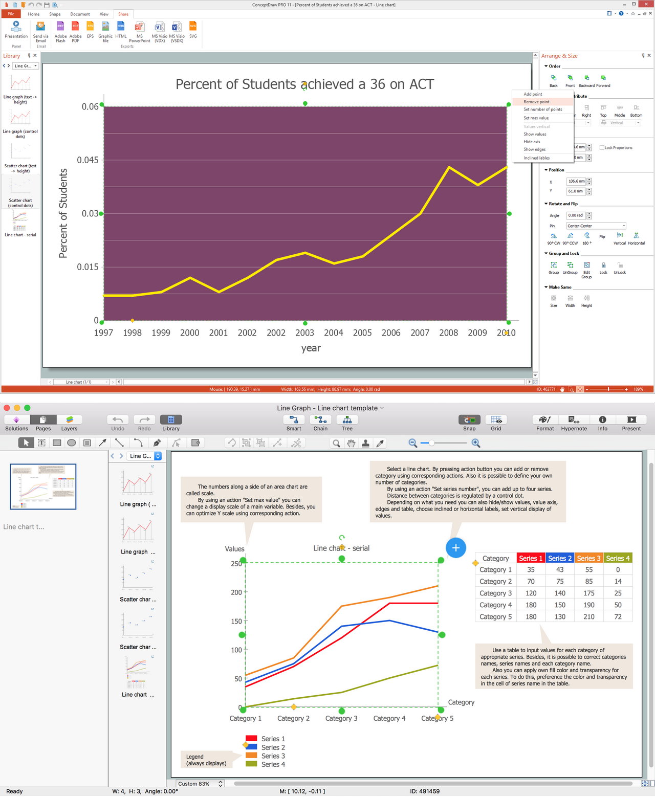
Example 2. Line Graph in ConceptDrae PRO
Having “Example 1: Line Graph — Relative Price Changes”, “Example 2: Line Graph — Number of Airlinges Departures in the Given Years”, “Example 3: Line Graph — France Export of Goods and Services”, “Example 4: Line Graph — Spets Walked in a Week”, “Example 5: Line Graph — Percent of Students a 36 on ACT”, as well as other templates, such as the “Line Graph — Circuit Efficiency Erland B”, “Line Graph — 1918 Spanish Flu Waves”, “Veteran Point in Time Counts, 2009-2012” and “Wait Time for Treatment in Hospital Emergency Department” any ConceptDraw DIAGRAM user can edit any mentioned above sample to make their own drawing.