Financial Trade UML Use Case Diagram Example

This sample shows the work of the Financial Trade sphere and can be used by trading companies, commercial organizations, traders, different exchanges.
UML Use Case Diagram Example. Registration System

This sample was created in ConceptDraw DIAGRAM diagramming and vector drawing software using the UML Use Case Diagram library of the Rapid UML Solution from the Software Development area of ConceptDraw Solution Park.
This sample shows the types of user’s interactions with the system and is used at the registration and working with the database system.
Account Flowchart. Flowchart Examples
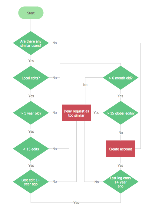
The flow chart example shows the computer network system account processing.
Bank UML Diagram

Diagramming Software for Design UML Use Case Diagrams


Diagramming Software for Design UML Collaboration Diagrams

UML Class Diagram Example - Apartment Plan

This sample show the detailed plan of the apartment and is used by building companies, design apartments, real estate agencies, at the buying / selling of the realty.
UML Use Case Diagram Example. Services UML Diagram. ATM system

This sample shows the scheme of the servicing using the ATMs (Automated Teller Machines) and is used at the working of ATM banking systems, at the performing of the banking transactions.
 ATM UML Diagrams
The ATM UML Diagrams solution lets you create ATM solutions and UML examples. Use ConceptDraw DIAGRAM as a UML diagram creator to visualize a banking system.
Use Case Diagrams technology with ConceptDraw DIAGRAM

- Class UML Diagram for Bank Account System | UML package ...
- ATM UML Diagrams | PM Dashboards | SYSML | Sequence ...
- Financial Trade UML Use Case Diagram Example | Process ...
- Class UML Diagram for Bank Account System | Bank UML Diagram ...
- ATM UML Diagrams | UML use case diagram - Banking system ...
- UML use case diagram - Banking system
- Bank System | Banking System | Class UML Diagram for Bank ...
- Bank Sequence Diagram | UML use case diagram - Banking system ...
- Uml Diagrams For Online Post Office Account Management System
- Class UML Diagram for Bank Account System | Bank Sequence ...
- ERD | Entity Relationship Diagrams, ERD Software for Mac and Win
- Flowchart | Basic Flowchart Symbols and Meaning
- Flowchart | Flowchart Design - Symbols, Shapes, Stencils and Icons
- Flowchart | Flow Chart Symbols
- Electrical | Electrical Drawing - Wiring and Circuits Schematics
- Flowchart | Common Flowchart Symbols
- Flowchart | Common Flowchart Symbols