Types of Flowcharts
There are many tools for managing a process or illustrating an algorithm or a workflow. Flowcharting is one of those tools. A Flowchart is a type of diagram that represents an algorithm, workflow, or process, showing the steps as boxes of various kinds, and their order by connecting them with arrows.
It may be difficult to show complex processes that require multiple attributes or several people in a simple Flowchart, so a Cross-functional flowchart would be a solution for that situation. For other conditions, a variety of types of Flowchart is prescribed.
If you ever tried programming, you could face a lot of problems as a beginner. To help yourself, create a Flowchart to follow an algorithm logic. A Flowchart diagram represents a program as a sequence of steps depicted in special symbols for each type of action.
Creating a Flow chart in order to help your business processes run the way you want them to, or simply making them in order to understand some process itself, can be very useful if you have the best flowchart software ConceptDraw DIAGRAM. It is the tool for drawing the Flowcharts which can be helpful in:
- defining processes;
- clarifying documentation process;
- building processes in order to have a visual representation for analysis, discussion, and communication;
- identifying the scope of the process;
- tracing and analyzing process steps;
- standardizing and finding areas for monitoring, improvement, and increased efficiency in some processes;
- finding and detaching all the steps of some process that are not essential;
- understanding the logic of some complex problems;
- overseeing operations;
- facilitating communications between programmers and businessmen;
- writing programs of any complexity in any high-level language;
- improving teamwork effectiveness;
- debugging processes;
- providing efficient programs of maintenance;
- understanding and explaining to others the logic of some complex problems and solutions to them.
ConceptDraw DIAGRAM is a professional flowchart design application for quick creating great-looking Flowcharts. Making a Flowchart with the Flowcharts solution or other solutions from the ConceptDraw Solution Park is simple and it takes only a couple of minutes to finish this work in case you have all the templates needed as well as the elements that you can find in the solution libraries.
The vector stencils from object libraries allow you to use the RapidDraw technology. By clicking on the direction arrows one can add a new object to the Flowchart. This technology gives users the ability to create visualization for the structural data quickly.
Here are brief summaries of the common uses of flowcharts and types of diagrams typically associated with them.

Basic Flowchart
Basic Flowchart is a simple diagram of the step-by-step execution of an algorithm. It is used at the lowest level of business model description. Basic Flowchart is very simple and visual for creating and understanding. The simple algorithm shapes that represent the processes steps are used for creating the Basic Flowcharts and are connected by arrows that show the order of operations.
Basic Flowcharts are widely used in different areas of knowledge. But they also have some disadvantages: the set of graphic elements is very limited, for example, the participants of the business process are not marked on the chart.
- Planning a new project.
- Represents an algorithm or process.
- Illustrates a solution to a given problem.
- Represented process operations.
- Used in analyzing.
- Used in designing.
- Used in documenting.
- Used in managing a process.
- Used in programs in various fields.

Example 1. Basic Flowchart
Business Process Modeling Diagram
Business Process Modeling Notation (BPMN) is a standardized graphical notation that allows the creation of a graphical view of the business processes in a workflow. BPMN standard notation was developed by the Business Process Management Initiative (BPMI) to unify the expression of the business processes and to help all business users easily understand each other using the unified standard. It is a simple and visual tool for businesses and business processes, the common standard for the design and implementation of business processes.
In 2011 the BPMN 2.0 was standardized. Until then version 1.1 was used.
- Analytical representation of business processes.
- Illustrating business processes of an organization.
- Bridging the communication gap between business process design and implementation.
- Simplifying understanding of business activities flows and processes.
- Showing internal business processes to a specific organization.
- Depicting the interactions between two or more business entities.
- Process improvement.
")
Example 2. Business Process Diagram (BPMN)
Cross-Functional Flowchart
Cross-Functional Flowchart (also called Deployment Flowchart) is a notation that is used to show the processes on the lower level of the business model. Cross Functional Flowchart displays the detailed algorithm of the business process execution, the participants of the process, and the interactions between them.
Cross Functional Flowcharts use the swim lanes that represent the functional units and can be arranged horizontally or vertically. In a horizontal layout, bands representing functional units run horizontally across the drawing page, highlighting the process. In a vertical layout, bands representing the functional units run vertically from the top to the bottom of the page, highlighting the functional units.
Cross Functional Flowcharts are very simple and useful, but demand a certain degree of detail. They are often used as the tool of the business planning. The use of the Cross-Functional Flowchart is a clear way of showing each team member’s responsibilities and how processes get shared or transferred between different responsible people, teams, and departments.
- Visualization and communication of the operations of a business process flow step-by-step.
- Depicting responsible people or departments for each operation.
- Simplifying understanding of business activities flows and processes.

Example 3. Cross-Functional Flowchart
Data Flow Diagram (DFD)
Data Flow Diagram (DFD) is one of the main tools for structural analysis and design of the information systems. Data Flow Diagram graphically represents how the information system works and develops, the interactions between the system and external data sources in terms of data flows, and the data flows that the information system receives from the outside.
The DFD Model is a hierarchical model. Each process may be subjected to decomposition, i.e. divided into the structural components, the relationships between them in the same notation can be shown on the separate diagram.
Two notations are used for describing the DFDs: Yourdon & Coad and Gane & Sarson.
- Data management.
- Graphical representation of the "flow" of data through an information system.
- Modeling process aspects.
- An overview of the system.
- Visualization of data processing (structured design).
- What kinds of information will be input to and output from the system.
- Where the data will come from and go to.
- Where the data will be stored.
")
Example 4. Data Flow Diagram (DFD)
Event-driven Process Chain (EPC) Diagram
Event-Driven Process Chain (EPC) Diagram is a flowchart of business process modeling that uses Events and Functions as key elements. EPC Diagram must start and end by the event. The function should always follow the event, i.e. the function creates a certain event (state). Documents, organizational units, process owners, information and control flows, and elements of the information system have their graphic symbols. The various connectors are provided. For branching of the process are used the logical operators AND, OR, XOR.
The Event-driven Process Chain method was developed within the framework of the ARIS (Architecture of Integrated Information Systems) that is used by a large number of companies for business process modeling, analyzing, and redesigning.
EPC is used on the lower levels of business model description when you need to describe the detailed step-by-step execution of the business process, all executors, and used objects. Event-driven Process Chain Diagrams are simple and easy to understand. They are widely used in the IT field and software development. But it is needed the special stuff training for creating and understanding of EPC Diagrams. It is a disadvantage of this type of Flowcharts.
- Modeling a business process.
- Enterprise resource planning.
- Business process improvement.
- Business process implementation.

Example 5. Event-driven Process Chain (EPC) Diagram
IDEF Flowchart
IDEF (Integrated DEFinition) is a methodology of modeling complex systems in the field of software engineering. IDEF diagrams were introduced in 1981 as a part of the ICAM (Integrated Computer-Aided Manufacturing) project.
The IDEF family includes the IDEF0 - IDEF14 methods, which have a wide range of uses, such as functional modeling, object-oriented analysis and design, and knowledge attainment. IDEF0, IDEF1X, and IDEF3 are the most used and widely recognized components of the IDEF family.
IDEF0 is a functional modeling method that describes the business processes, models the decisions, actions, and activities of the complex system or organization. IDEF0 is based on the SADT (Structured Analysis and Design Technique). It is the result of the program of industry computerization, which was proposed by the US Air Force. IDEF0 notation was standardized in 1993 by the National Institute of Standards and Technology of the United States Department of Commerce.
- Create function models
- Develop transition schematics
- Design system architecture
- Database design
- Object-oriented design

Example 6. IDEF Flowchart
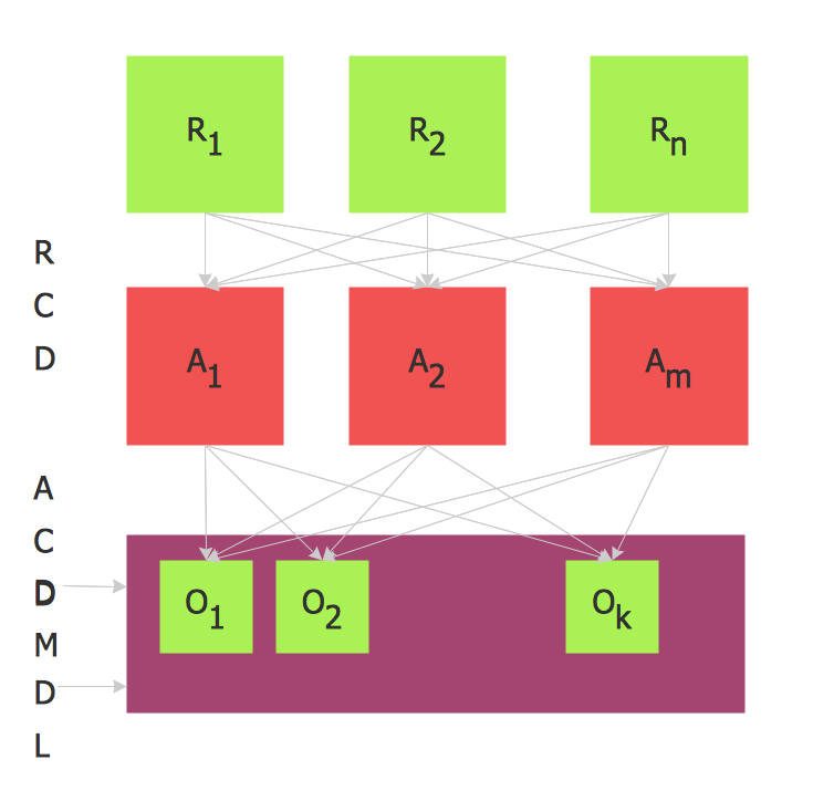
Influence Diagram (ID)
Influence diagram (ID) is a graphical and mathematical representation of the decision. It is a generalization of the Bayesian network. Influence diagrams are hierarchical. They are the alternative to the decision tree.
Influence diagram represents the directed acyclic graph with three types of nodes (Decision node, Uncertainty node, Value node) and three types of arcs that connect the nodes (Functional arcs, Conditional arcs, Informational arcs).
Influence diagrams are widely used in decision analysis and game theory.
")
Example 7. Influence Diagram (ID)
Swimlane Flowchart
The business processes in each company are allotted among workers and departments. The same process may be fulfilled by several workers simultaneously or by turns. In such cases, when it is quite difficult to define the reasons of delays, defects, and narrow places during the process, the documentation of business processes in the company is required. Swim Lane diagram is one of the tools for documenting business processes.
- Documenting a process.
- Mechanism to organize activities into separate visual categories.
- Illustrate different functional capabilities or responsibilities (organizational roles).

Example 8. Swimlane Flowchart
Process Flow Diagram (PFD)
Process Flow Diagram (PFD) is a flowchart that illustrates the high-level processes in chemical industry and process engineering. PFD displays only the major plant processes not focusing on the insignificant details or components.
Process Flow Chart can show single or multiple processes. PFD that displays multiple processes is called a schematic flow diagram or block flow diagram.
- Oil and petroleum refining.
- Natural gas systems.
- Green energy, such as wind and solar power.
- Water treatment and processes.
- Electrical power plants.
- Piping and irrigation systems.
-crude-oil-distillation-unit-pfd.png "Process Flow Diagram (PFD)")
Example 9. Process Flow Diagram (PFD)
Specification and Description Language (SDL) Diagram
Specification and Description Language (SDL) is a specification language for creating specifications, descriptions of the behavior, data, and inheritance for real-time systems. SDL is used for creating object-oriented diagrams, visualizing the processes of the state machines for the systems of communication, telecommunication, automotive, aviation, and medical industries.
Specification and Description Language provides the graphical Graphic Representation (SDL/GR) and the textual Phrase Representation (SDL/PR).
For creating the SDL diagrams the building blocks such as system definition, block agent, and process are used. Block agents consist of the process agents and communicate using the channels. A process agent is a state machine. A few block agents form the system agent. The message to the agent from another agent or the environment is called a signal and is placed in a queue (the input port).
- Mapping computer algorithms.
- Design SDL Diagram.
- Develop FSM Diagram.
- System Design.
- Systems Engineering.
- Build a real-time system involved in parallel processing.
 Diagram")
Example 10. Specification and Description Language (SDL) Diagram
Value Stream Mapping (VSM)
Value stream mapping supports the methods of lean manufacturing that are used for the analysis and design of the flow of the materials and information at the system level. This as a result brings the product or service to the consumer. The lead time is a key indicator associated with the value stream mapping.
Value stream mapping is widely used in manufacturing, logistics, product development, software development, healthcare, and other service industries. It is also used as a part of the Six Sigma methodologies.
- Analyze the current process.
- Acilitate future state maps.
- Make it easier to engage the extended team.
- Clearer presentation of the current state.

Example 11. Value Stream Map
Workflow Diagram
Workflow Diagram is a graphical description of the information flows, the relationships between the processes of information processing, and the objects that are the part of these processes. Workflow Diagram describes the stages of the business or manufacturing processes from the initial to the final stage allowing the organization to trace the progress of the processes quickly and clearly.
The following shapes are used for drawing the Workflow Diagrams: ovals that represent the workflow begin and end, rectangles that show the process activity, circles that show the connectors from one activity to another, and diamonds that signify the process of decision making.
Workflow Diagrams are an important part of business process management (BPM).
- Managing workflow.
- Show a pictorial overview of a business, technical, or functional process step-by-step.
- Model business process to develop, implement, reuse, analyze, solve problems, and improve the process.
- Simplify process collaboration by showing workflow in a chain of people and business units.
- Visualize control and information flow, business process automation, business process re-engineering, accounting, management, and HR tasks.
- Document business processes in 6 Sigma or ISO 9000.

Example 12. Workflow Diagram

Example 12. Types of Flowcharts
Conclusion
There are twelve main Flowchart types: Basic Flowchart, Business Process Modeling Diagram (BPMN), Cross Functional Flowchart, Data Flow Diagram (DFD), IDEF (Integrated DEFinition) Flowchart, Event-driven Process Chain (EPC) Diagram, Influence Diagram (ID), Swimlane Flowchart, Process Flow Diagram (PFD), Specification and Description Language (SDL) Diagram, Value Stream Mapping (VSM), Workflow Diagram. Using the ConceptDraw DIAGRAM software and its Flowcharts solution from the Diagrams area of ConceptDraw Solution Park, you can easily and quickly design a Flowchart of any of these types. The special predesigned vector symbols for each of these widely used notations will make the process of drawing Flowcharts much easier than ever.