Local area network (LAN). Computer and Network Examples


How To use House Electrical Plan Software


Metropolitan area networks (MAN). Computer and Network Examples

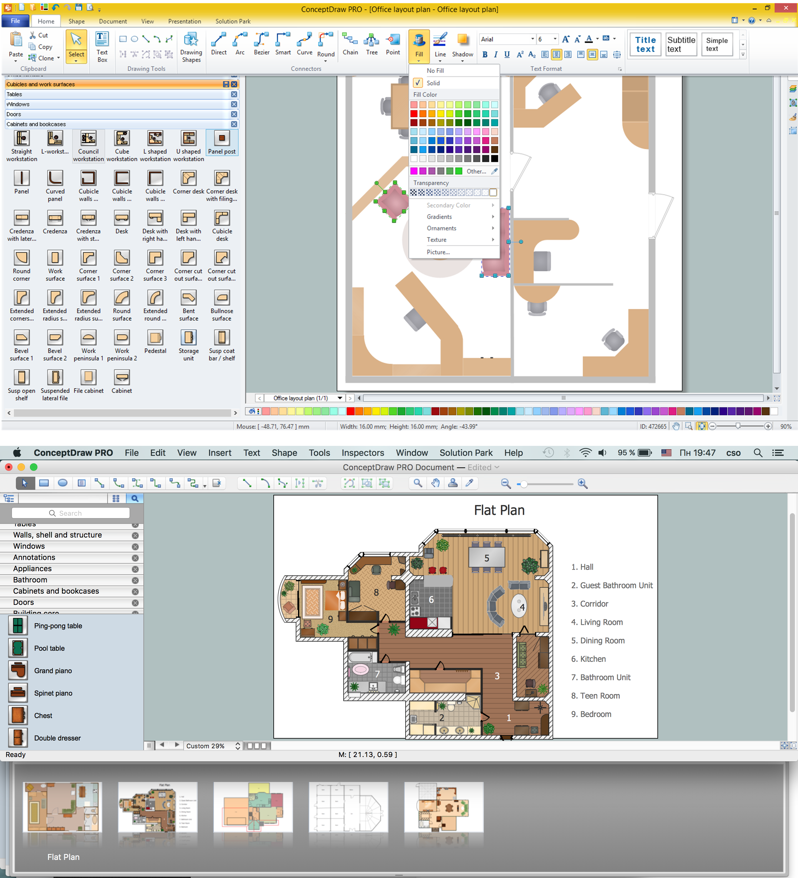
 Network Layout Floor Plans
Network Layout Floor Plans solution extends ConceptDraw DIAGRAM software functionality with powerful tools for quick and efficient documentation the network equipment and displaying its location on the professionally designed Network Layout Floor Plans. Never before creation of Network Layout Floor Plans, Network Communication Plans, Network Topologies Plans and Network Topology Maps was not so easy, convenient and fast as with predesigned templates, samples, examples and comprehensive set of vector design elements included to the Network Layout Floor Plans solution. All listed types of plans will be a good support for the future correct cabling and installation of network equipment.
Electrical Symbols, Electrical Diagram Symbols

How To Draw Building Plans

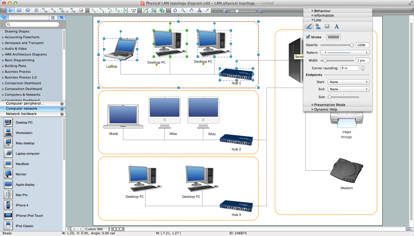
Network Diagram Software LAN Network Diagrams & Diagrams for LAN Physical Office Network Diagrams
Types of Flowchart - Overview


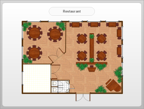
How To Create Restaurant Floor Plan in Minutes

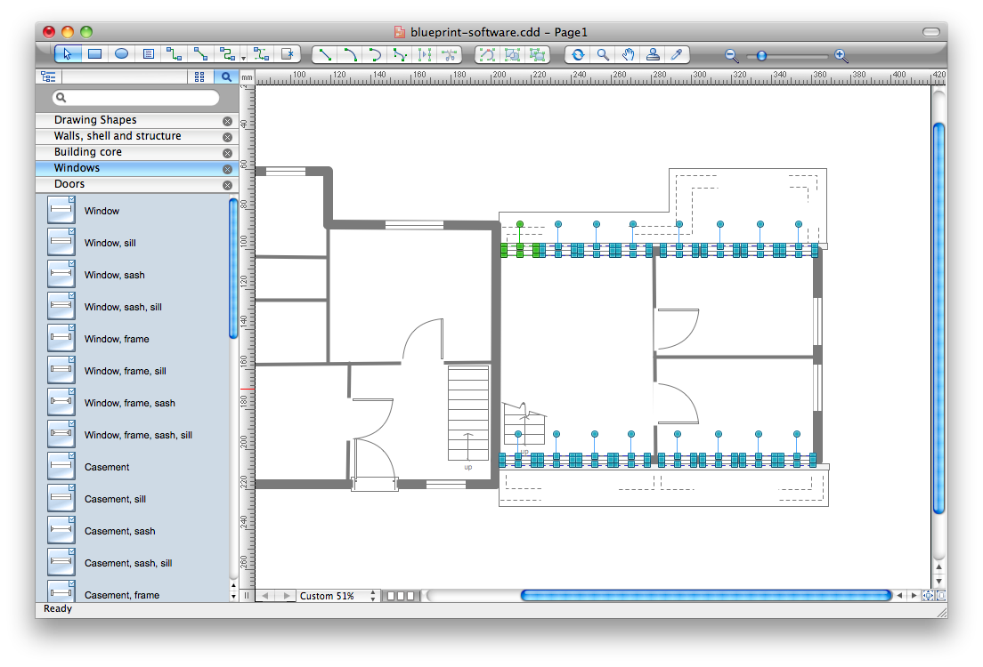
Blueprint Software
- Building Construction A Paragraph Within 100words
- Write A Paragraph Building Is Constructed
- Use The Following Flow Chart To Write A Paragraph Within 100
- Line Chart Template for Word | Write A Paragraph Within 100 Words ...
- Block Diagrams | Paragraph How Is A Building Is Constructed
- A Paragraph On How A Building Is Constructed Within 100 Words
- Write A Paragraph With In 100 Words On How To Make Paper
- Write Paragraph On How A Building Is Construced
- The Following Flow Chart To Write Out A Paragraph On How A
- Use The Following Flowchart To Write Paragraph Within 100 Word