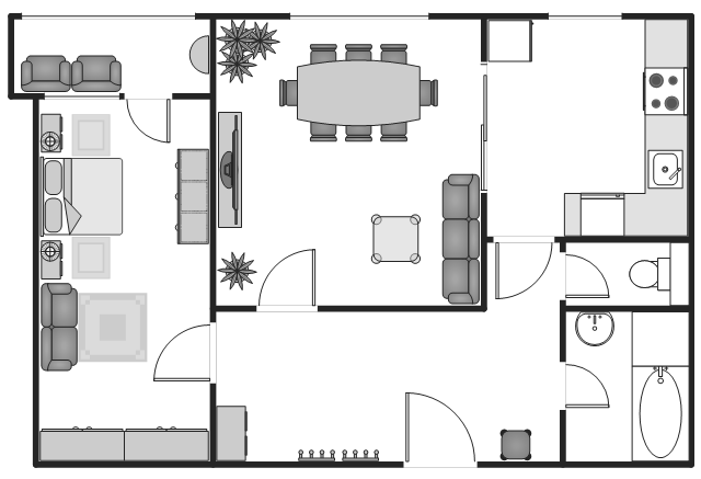
The Apartment plan example shows the layout of furniture, kitchen equipment and bathroom appliance on the interioir design floor plan.
"An apartment (in American English) or flat in British English is a self-contained housing unit (a type of residential real estate) that occupies only part of a building. Such a building may be called an apartment building, apartment house (in American English), block of flats, tower block, high-rise or, occasionally mansion block (in British English), especially if it consists of many apartments for rent." [Apartment. Wikipedia]
The Apartment plan example was created using ConceptDraw PRO diagramming and vector drawing software extended with the Basic Floor Plans solution from the Building Plans area of ConceptDraw Solution Park.
Flat plan
Diagramming Software for Design UML Collaboration Diagrams


Network Topologies


Mesh Network Topology Diagram

UML State Machine Diagram.Design Elements

Network Topologies
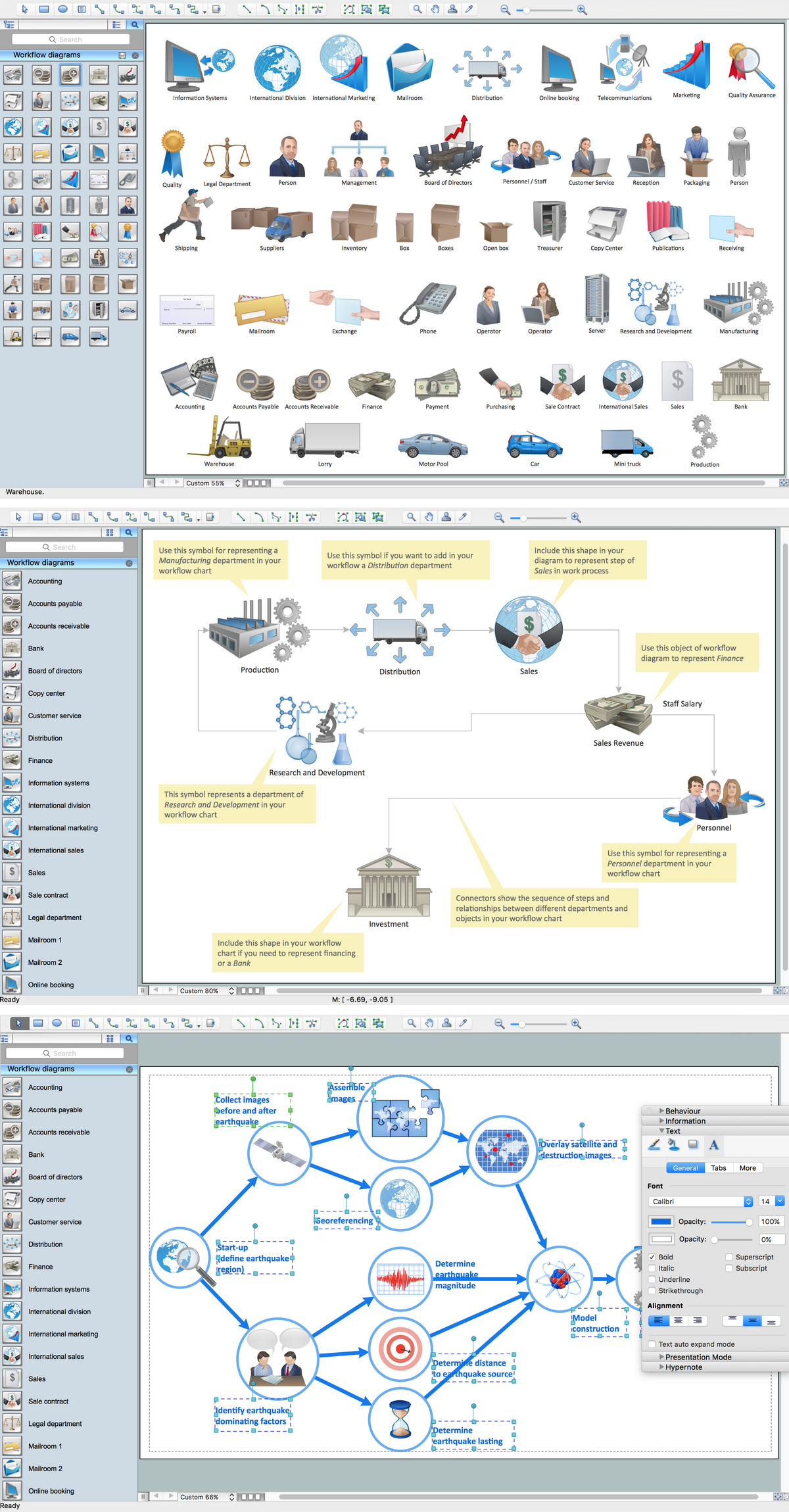
 Workflow Diagrams
Workflow Diagrams solution extends ConceptDraw DIAGRAM software with samples, templates and vector stencils library for drawing the work process flowcharts.
Workflow Diagram Software Mac
ERD Symbols and Meanings


UML Object Diagram. Design Elements

- Wiring Diagram For Three Bed Room Self Contain
- Wiring Diagram Of A 4 Bed Room Self Contain
- Wiring Diagram For A Single Room Self Contained
- Electrical Wiring Diagram Of A Room And Parlor Selfcontain
- Picture And Diagram Of How To Wire Self Contain Apartment
- Electrical Wiring Diagrem For A Self Contain House
- Electrical Wiring For A Selfcontain Single Room
- Creative classroom floor plan | Plan For Single Room Self Contain
- Website Wireframe | Cooking Recipes | How To Wire Three Rooms
- The Diagram Of Room And Parlour Self Contain