Entity-Relationship Diagram (ERD) with ConceptDraw DIAGRAM


Databases Access Objects Model with ConceptDraw DIAGRAM

Flowchart Symbols Accounting. Activity-based costing (ABC) flowchart
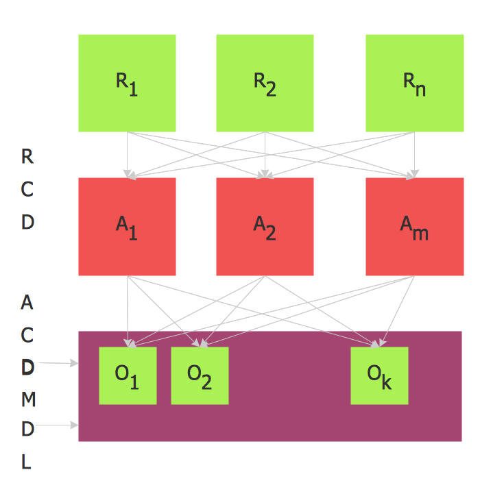
PROBLEM ANALYSIS. Relations Diagram


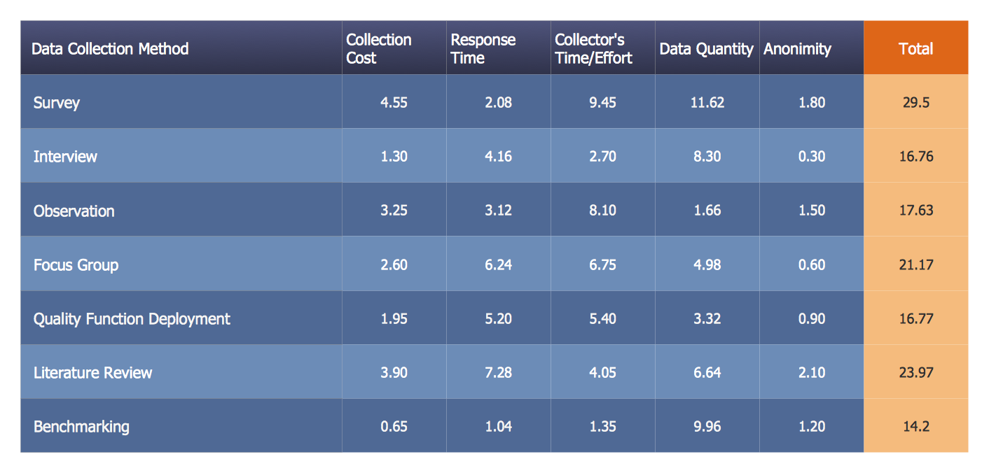
PROBLEM ANALYSIS. Prioritization Matrix
The vector stencils library "Network layout floorplan" contain 34 symbol icons for drawing computer network floor plans and communication equipment and cabling layouts.
"Networking hardware may also be known as network equipment or computer networking devices. Units which are the last receiver or generate data are called hosts or data terminal equipment.
All these terms refer to devices facilitating the use of a computer network. Specifically, they mediate data in a computer network. ...
Typically, networking hardware includes gateways, routers, network bridges, switches, hubs, and repeaters. But it also includes hybrid network devices such as multilayer switches, protocol converters, bridge routers, proxy servers, firewalls, network address translators, multiplexers, network interface controllers, wireless network interface controllers, modems, ISDN terminal adapters, line drivers, wireless access points, networking cables and other related hardware.
The most common kind of networking hardware today is a copper-based Ethernet adapter because of its standard inclusion on most modern computer systems. Wireless networking has, however, become increasingly popular, especially for portable and handheld devices.
Other hardware prevalent in computer networking includes data center equipment (such as file servers, database servers and storage areas), network services (such as DNS, DHCP, email, etc.) as well as devices which assure content delivery." [Networking hardware. Wikipedia]
The shapes example "Design elements - Network layout floorplan" was created using the ConceptDraw PRO diagramming and vector drawing software extended with the Network Layout Floor Plans solution from the Computer and Networks area of ConceptDraw Solution Park.
Network layout floor plan symbols

Applications

Bar Diagrams for Problem Solving. Create event management bar charts with Bar Graphs Solution

- Food - Vector stencils library | Windows 8 apps - Vector stencils ...
- Design elements - Doors and windows | Design elements - Walls ...
- Window Symbols And Meanings
- Cubicle layout | Design elements - Doors and windows
- Window Symbols On A Floor Plan
- Process Flowchart | Workflow Diagrams | Workflow Diagram ...
- Cisco LAN fault-tolerance system - diagram
- Walls, shell and structure - Vector stencils library | Design elements ...
- Taxi order process - BPMN 1.2 diagram | Taxi service order ...
- Lan Computer Diagram
- Workflow Diagrams | Sales Process Flowchart. Flowchart Examples ...
- Business Process Diagram | Business Process Modeling Tools ...
- Basic Flowchart Symbols and Meaning | How to Create Flowchart ...
- Taxi service order procedure - BPMN 1.2 diagram | Taxi Service ...
- ConceptDraw Solution Park | Professions - Vector stencils library ...
- Network Layout Floor Plans | Ethernet local area network layout floor ...
- Data Flow Diagram Symbols. DFD Library | Basic Flowchart ...
- Presentation Clipart | Benefits and cons of car leasing - Presentation ...
- Software Defined Networking System Overview ...
- Network Layout Floor Plans | Design elements - Network layout ...