JSD - Jackson system development

How to Draw ER Diagrams

Jacobson Use Cases Diagram

SDL Diagram

Agile Methodology

 Jackson Structured Programming (JSP) Diagrams
The Jackson Structured Programming (JSP) Diagram solution extends the functionality and drawing abilities of the ConceptDraw DIAGRAM software with set of illustrative JSP diagrams samples and large variety of predesigned vector objects of actions, processes, procedures, selection, iteration, as well as arrows and connectors to join the objects during Jackson structured development and designing Jackson structured programming diagrams, JSP diagram, Jackson structure diagram (JSD), Program structure diagram. The powerful abilities of this solution make the ConceptDraw DIAGRAM ideal assistant for programmers, software developers, structural programmers, computer engineers, applications constructors, designers, specialists in structured programming and Jackson systems design, and other technical, computer and software specialists.
Jackson Systems

Business Process Flow Diagram

System Design

 Software Development Area
Solutions from the Software Development Area of ConceptDraw Solution Park collect templates, samples and libraries of vector stencils for drawing the software engineering diagrams and user interface design prototypes.
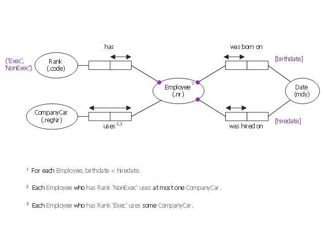
This object-role modeling (ORM) diagram sample shows model of employee data: birthdate, hiredate, rank, company car number. It was designed on the base of the Wikimedia Commons file: ORM-diagram-tkz-orm.png. [commons.wikimedia.org/ wiki/ File:ORM-diagram-tkz-orm.png]
"Facts.
Object-role models are based on elementary facts, and expressed in diagrams that can be verbalised into natural language. ...
This "fact-based" approach facilitates modeling, transforming, and querying information from any domain. ...
Attribute-free.
ORM is attribute-free: unlike models in the entity–relationship (ER) and Unified Modeling Language (UML) methods, ORM treats all elementary facts as relationships and so treats decisions for grouping facts into structures (e.g. attribute-based entity types, classes, relation schemes, XML schemas) as implementation concerns irrelevant to semantics. By avoiding attributes in the base model, ORM improves semantic stability and enables verbalization into natural language. ...
Fact-based modeling.
Fact-based modeling includes procedures for mapping facts to attribute-based structures, such as those of ER or UML. ...
Fact-based graphical notations are more expressive than those of ER and UML. ...
Design procedure.
System development typically involves several stages such as: feasibility study; requirements analysis; conceptual design of data and operations; logical design; external design; prototyping; internal design and implementation; testing and validation; and maintenance." [Object-role modeling. Wikipedia]
The object-role modeling diagram example "Employee ORM diagram" was designed using ConceptDraw PRO software extended with ORM Diagrams solution from Software Development area of ConceptDraw PRO Solution Park.
Object-role model
- JSD - Jackson system development | Agile Methodology | ER ...
- JSD - Jackson system development | ER Diagram Styles | Agile ...
- JSD - Jackson system development | Data structure diagram with ...
- JSD - Jackson system development | Example of DFD for Online ...
- JSD - Jackson system development | ERD Symbols and Meanings ...
- Process Flowchart | JSD - Jackson system development | Systems ...
- JSD - Jackson system development | Drawing ER diagrams on a ...
- ERD Symbols and Meanings | JSD - Jackson system development ...
- JSD - Jackson system development | Agile Methodology ...
- JSD - Jackson system development | Data Flow Diagram | Jackson ...
- Process Flowchart | Systems development life cycle | JSD - Jackson ...
- JSD - Jackson system development | Data Flow Diagram Example ...
- Data Flow Diagram | JSD - Jackson system development ...
- Structured Systems Analysis and Design Method. SSADM with ...
- Data Modeling with Entity Relationship Diagram | Components of ...
- Systems development life cycle | Process Flowchart | JSD - Jackson ...
- Structured Systems Analysis and Design Method. SSADM with ...
- Structured Systems Analysis and Design Method (SSADM) with ...
- Structured Systems Analysis and Design Method. SSADM with ...
- Yourdon and Coad Diagram | Structured Systems Analysis and ...