Example of DFD for Online Store (Data Flow Diagram)


DFD Flowchart Symbols

ER Diagram for Cloud Computing

Booch OOD Diagram

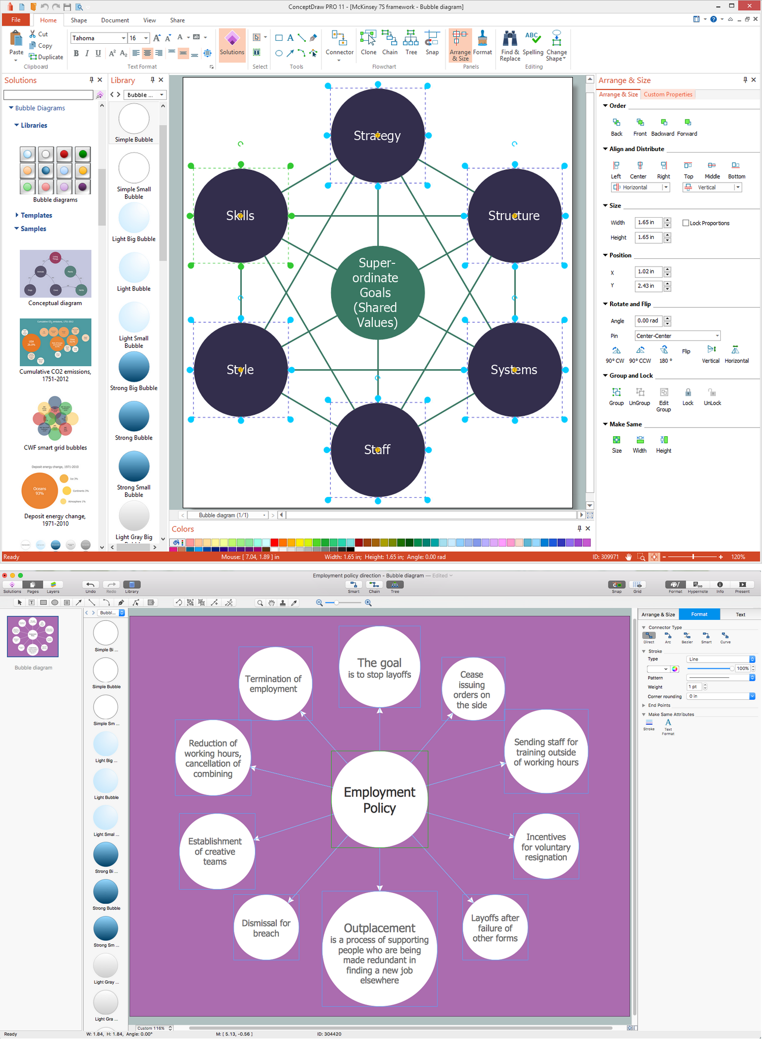
Bubble Chart
How to create a UML Diagram

Jacobson Use Cases Diagram

UML Class Diagram Notation

Bubble Chart Maker
How to create your UML Diagram

Accounting Flowchart Symbols

- Er Diagram For Medical Store Management System
- Er Model For Medical Management System
- Use Case Diagram For Pharmacy Management System
- UML Class Diagram Example - Medical Shop | Entity -Relationship ...
- Uml Diagram For Medical Management System
- Er Diagram Of Medicine Store Management System
- Shop Management System Uml Diagrams
- Er Diagram Of Medical Store Step By Step Showing System
- Structure Diagram Of Pharmacy Management System
- Class Diagram For Online Pharmacy Management System
- Er Diagram Of Shop Management System
- Entities Involved In Medical Shop Management
- Use Case Diagram For Medical Store Management System
- Dfd Diagram From Medical Store Management
- Er Diagram For Healthcare Management System
- Entity Relationship Diagram Tables Of Pharmacy Management System
- Er And Dfd For Shop Management System
- Uml Diagram For Drug Management System
- Data Flow Diagram Of Medical Store Management System
- Medical Management Class Diagram