HelpDesk
How to Add and Edit Connector Text

Use this template to prototype and design the wireframe graphic user interface (GUI).
"A website wireframe, also known as a page schematic or screen blueprint, is a visual guide that represents the skeletal framework of a website. Wireframes are created for the purpose of arranging elements to best accomplish a particular purpose. The purpose is usually being informed by a business objective and a creative idea. The wireframe depicts the page layout or arrangement of the website’s content, including interface elements and navigational systems, and how they work together. The wireframe usually lacks typographic style, color, or graphics, since the main focus lies in functionality, behavior, and priority of content. In other words, it focuses on what a screen does, not what it looks like. Wireframes can be pencil drawings or sketches on a whiteboard, or they can be produced by means of a broad array of free or commercial software applications. Wireframes are generally created by business analysts, user experience designers, developers, visual designers and other roles with expertise in interaction design, information architecture and user research.
Wireframes focus on:
(1) The kinds of information displayed.
(2) The range of functions available.
(3) The relative priorities of the information and functions.
(4) The rules for displaying certain kinds of information.
(5) The effect of different scenarios on the display.
The website wireframe connects the underlying conceptual structure, or information architecture, to the surface, or visual design of the website. Wireframes help establish functionality, and the relationships between different screen templates of a website. An iterative process, creating wireframes is an effective way to make rapid prototypes of pages, while measuring the practicality of a design concept. Wireframing typically begins between “high-level structural work - like flowcharts or site maps - and screen designs.” Within the process of building a website, wireframing is where thinking becomes tangible.
Aside from websites, wireframes are utilized for the prototyping of mobile sites, computer applications, or other screen-based products that involve human-computer interaction." [Website wireframe. Wikipedia]
The wireframe GUI template for the ConceptDraw PRO diagramming and vector drawing software is included in the Graphic User Interface solution from the Software Development area of ConceptDraw Solution Park.
Wireframe GUI template
ATM Solutions
Bank Sequence Diagram

HelpDesk
How to Create Digital Media Infographics

HelpDesk
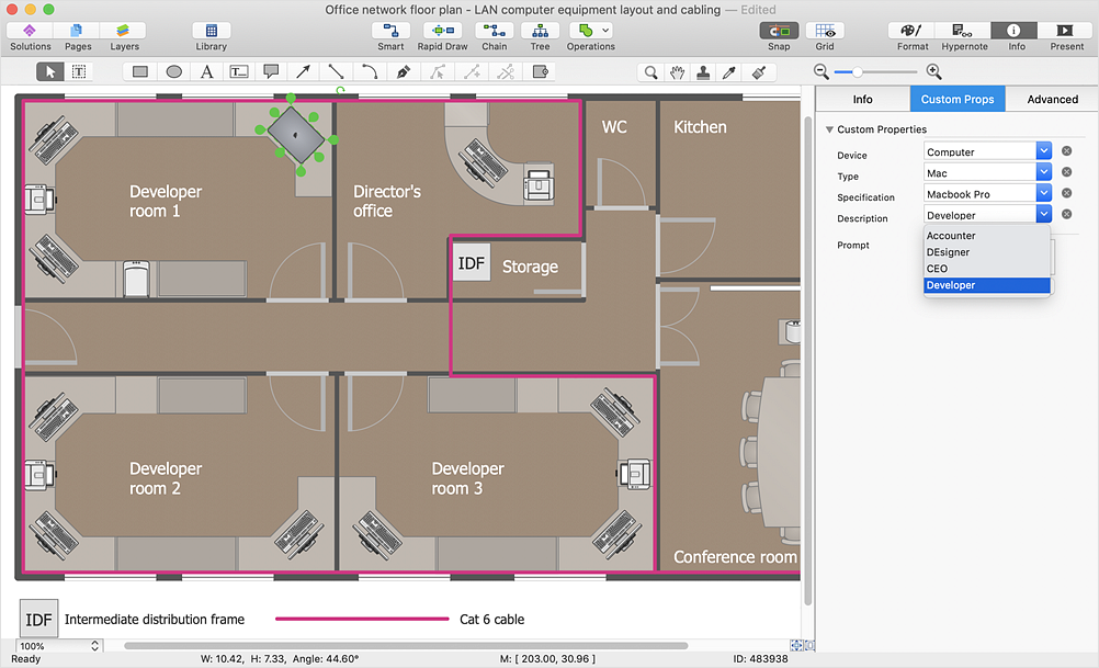
How to Work with Custom Properties
HelpDesk
How to Create an Enterprise Architecture Diagram

Electrical Diagram Software


HelpDesk
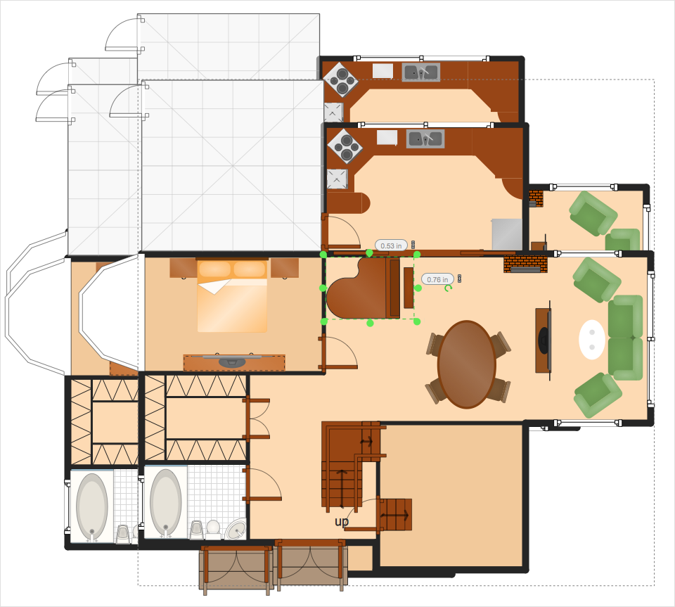
How to Resize Objects
Bank System
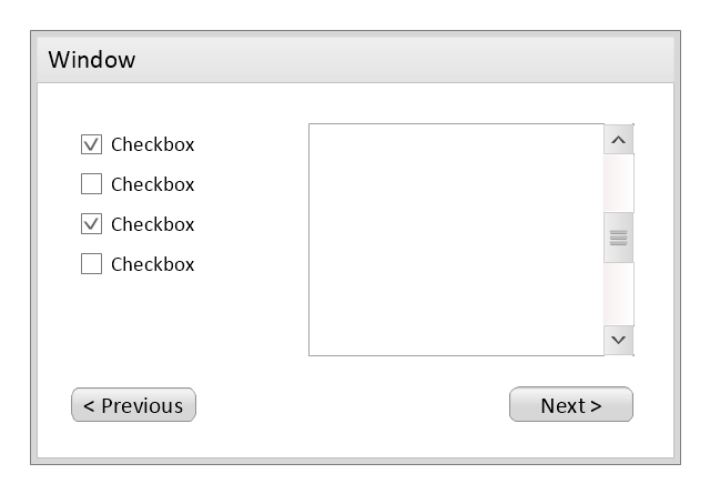
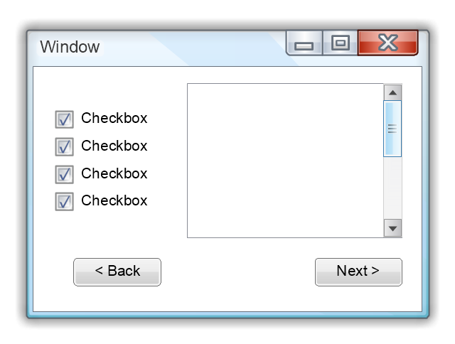
Use this template to prototype and design the Windows graphic user interface.
"In human–computer interaction, WIMP stands for "windows, icons, menus, pointer", denoting a style of interaction using these elements of the user interface. ... Other expansions are sometimes used, substituting "mouse" and "mice" or "pull-down menu" and "pointing", for menus and pointer, respectively. ...
In a WIMP system:
(1) A window runs a self-contained program, isolated from other programs that (if in a multi-program operating system) run at the same time in other windows.
(2) An icon acts as a shortcut to an action the computer performs (e.g., execute a program or task).
(3) A menu is a text or icon-based selection system that selects and executes programs or tasks.
(4) The pointer is an onscreen symbol that represents movement of a physical device that the user controls to select icons, data elements, etc.
(5) cut, copy, and paste.
This style of system improves human–computer interaction (HCI) by emulating real-world interactions and providing better ease of use for non-technical people - both novice and power users. Users can carry skill at a standardized interface from one application to another.
Due to the nature of the WIMP system, simple commands can be chained together to undertake a group of commands that would have taken several lines of command line instructions." [WIMP (computing). Wikipedia]
The Windows Vista graphic user interface template for the ConceptDraw PRO diagramming and vector drawing software is included in the Graphic User Interface solution from the Software Development area of ConceptDraw Solution Park.
Windows GUI template
Security Plans
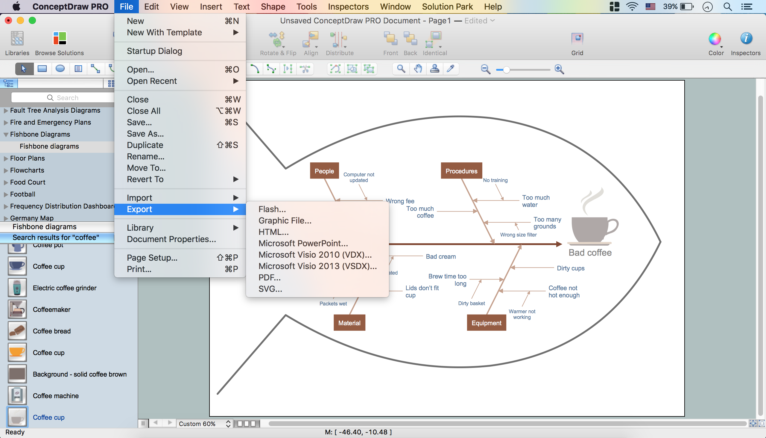
How to Construct a Fishbone Diagram
HelpDesk
How to Draw a Fishbone Diagram

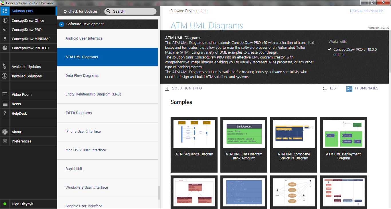
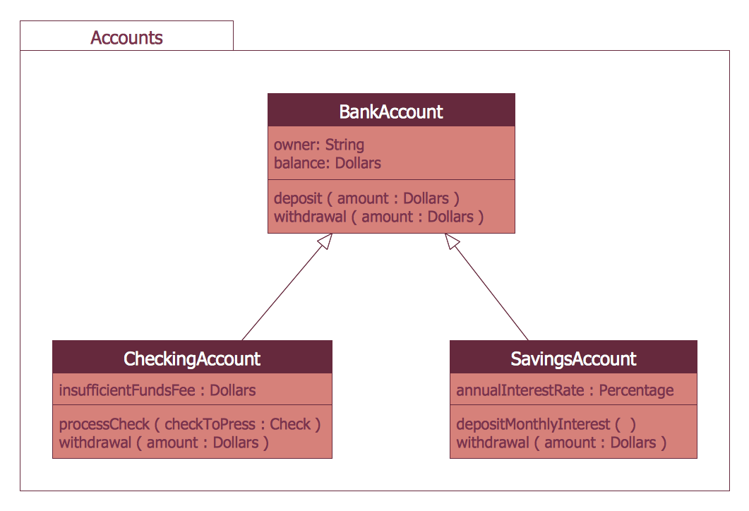
 ATM UML Diagrams
The ATM UML Diagrams solution lets you create ATM solutions and UML examples. Use ConceptDraw DIAGRAM as a UML diagram creator to visualize a banking system.
- Controls - Vector stencils library | MindTweet | Design elements ...
- Simple Corner Text Box
- MS Windows Vista user interface - Vector stencils library | Window ...
- How to Draw a Landscape Design Plan | Wireframe GUI - Template ...
- Website Wireframe | Design elements - Wireframe | How to Develop ...
- Azure Architecture | Instruments - Vector stencils library | SWOT ...
- Square Box Png
- MS Windows Vista user interface - Vector stencils library | Design ...
- Full-screen dialog | Messages - Template | OS X 10.10 Yosemite ...
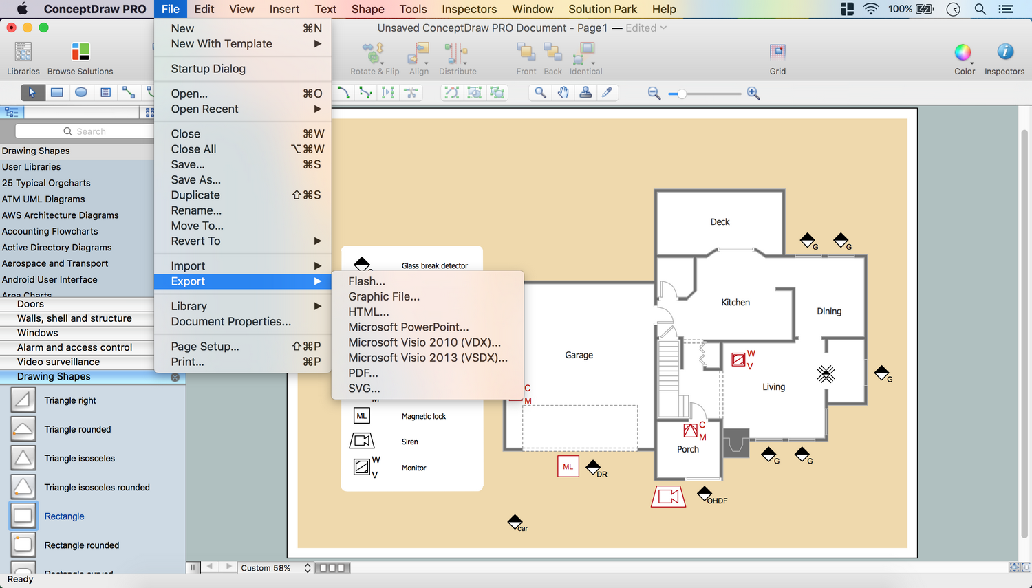
- Export from ConceptDraw PRO Document to a Graphic File | SWOT ...
- Sector diagram - Template | New Zealand Public Sector Agencies ...
- iPhone User Interface | Messages - Template | Design elements ...
- Check Boxes Png
- Map Australia | Positioning Map | ConceptDraw PRO 9 Comparison ...
- Plc Visio Templates
- User Interface Design Examples | GUI Prototyping with ...
- Bar Graphs | Basic Bar Graphs | Controls - Vector stencils library ...
- Concept Draw Pro How To Rotate Text Box
- Design elements - Text blocks | CMP adaptive management cycle ...
- Functional Block Diagram | Design elements - Text and Images ...