Diagramming Software for UML Composite Structure Diagrams


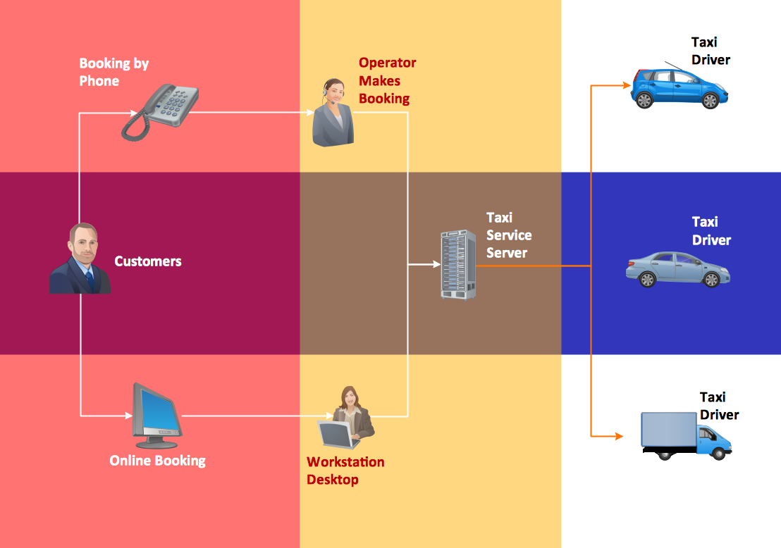
Taxi Service Data Flow Diagram DFD Example

HelpDesk
How to Create an Entity-Relationship Diagram

Workflow Process Example

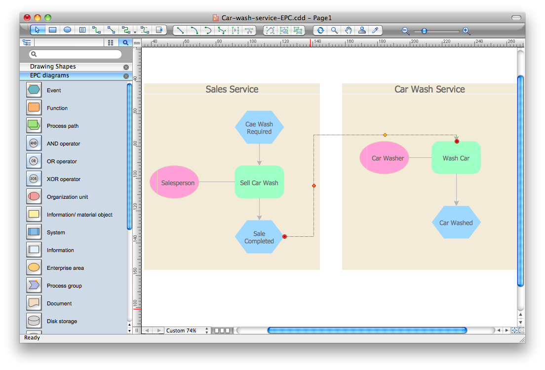
Event-Driven Process Chain Diagram Software
"Driving is the controlled operation and movement of a vehicle, such as a car, carriage, truck or bus. ...
Driving as a physical skill.
A driver must have physical skills to be able to control direction, acceleration, and deceleration. For motor vehicles, the detailed tasks include:
(1) Starting the vehicle's engine with the starting system.
(2) Setting the transmission to the correct gear.
(3) Depressing the pedals with one's feet to accelerate, slow, and stop the vehicle, and if the vehicle is equipped with a manual transmission, to modulate the clutch.
(4) Steering the vehicle's direction with the steering wheel.
(5) Operating other important ancillary devices such as the indicators, headlights, and windshield wipers.
(6) Observing the environment for hazards." [Driving. Wikipedia]
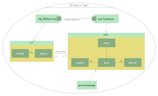
The UML composite structure diagram example "Drive a taxi" was created using the ConceptDraw PRO diagramming and vector drawing software extended with the Rapid UML solution from the Software Development area of ConceptDraw Solution Park.
Driving as a physical skill.
A driver must have physical skills to be able to control direction, acceleration, and deceleration. For motor vehicles, the detailed tasks include:
(1) Starting the vehicle's engine with the starting system.
(2) Setting the transmission to the correct gear.
(3) Depressing the pedals with one's feet to accelerate, slow, and stop the vehicle, and if the vehicle is equipped with a manual transmission, to modulate the clutch.
(4) Steering the vehicle's direction with the steering wheel.
(5) Operating other important ancillary devices such as the indicators, headlights, and windshield wipers.
(6) Observing the environment for hazards." [Driving. Wikipedia]
The UML composite structure diagram example "Drive a taxi" was created using the ConceptDraw PRO diagramming and vector drawing software extended with the Rapid UML solution from the Software Development area of ConceptDraw Solution Park.
UML composite structure diagram
How To Create a Workflow Diagram
Software Diagram Examples and Templates

UML Use Case Diagrams

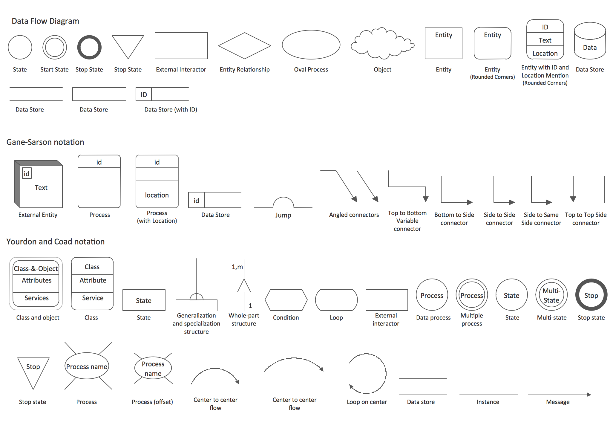
DFD Library — Design elements
- Diagram Taxi Erd
- Erd For Taxi Cab
- Cab Company Erd
- Cab Management System Project Erd And Dfds
- Taxi Service Data Flow Diagram DFD Example | UML Use Case ...
- Uber Comoqny Erd
- Er Diagram For Taxi Servis System
- Draw Erd Digram Online Cab Management
- Er Diagram For Cab Services
- Entity-relationship diagram (Crow's foot notation) | Erd Diagram Uber