HelpDesk
How to Create a Fault Tree Analysis Diagram (FTD)

ERD Symbols and Meanings


HelpDesk
Accounting Information Systems Flowchart Symbols

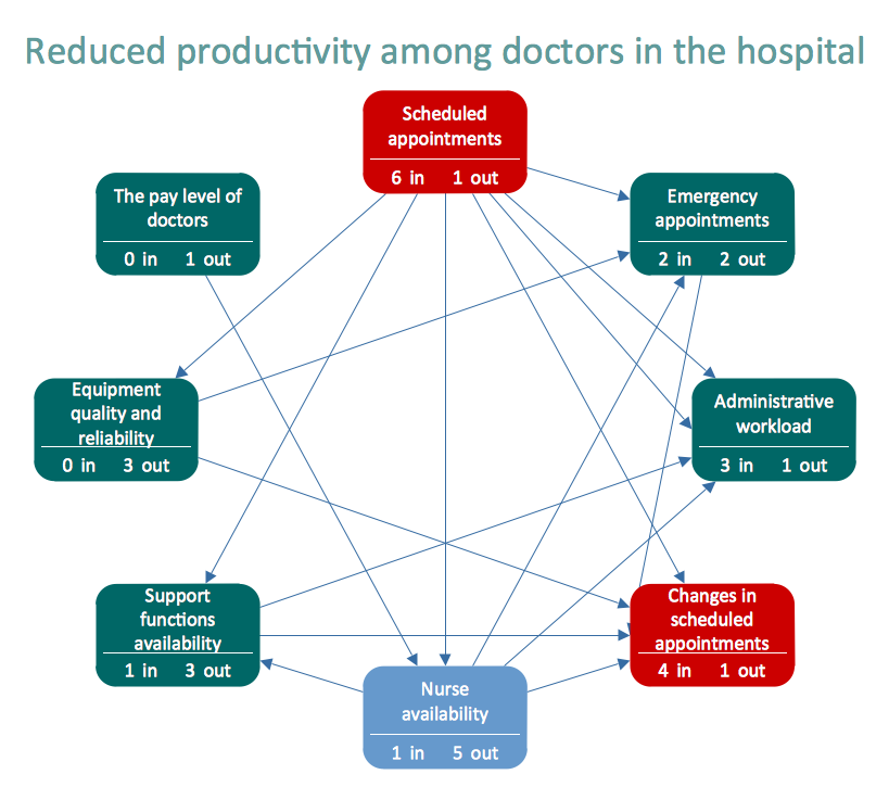
Relationships Analysis

Basic Flowchart Symbols and Meaning


Internet solutions with ConceptDraw DIAGRAM
Electrical Symbols — Inductors

 Genogram
Genogram solution including professionally designed genogram samples and a wide range of high-quality vector design elements of genogram symbols, medical genogram symbols, emotional relationships and family relationships, makes the ConceptDraw DIAGRAM software the best for drawing the informative Genograms, genealogy schematics and illustrations, and family tree of any depth, and for any quantity of generations. It perfectly suits for the medical specialists of different profiles, medical consultants, therapists, genetics, psychologists, and other medical professionals, each individual and couple.
Competitor Analysis

Cisco Network Topology. Cisco icons, shapes, stencils and symbols

- Site Analysis Symbols
- Site Analysis Symbols Png
- Graphic Symbol In Architecture Site Analysis
- Tree Symbols For Site Analysis
- AWS Architecture Diagrams | Azure Architecture | Site Analysis ...
- Architecture Site Analysis Arrow Png
- Site Analysis In Bubble Diagram
- Site Analysis Architecture Pdf
- Design elements - Fault tree analysis diagrams | Fault Tree Diagram ...
- Site accessories - Vector stencils library | Supermarket parking ...