Made with
ConceptDraw
DIAGRAM 18

Internet solutions with ConceptDraw DIAGRAM

Only ConceptDraw PRO v 5, 6 is supported.

If you are interested in such functionality, leave a request, and we will take into account your wishes when developing new versions.

What may interest developers of Internet solutions in ConceptDraw?

Internet can be viewed as some resources (web-pages, files, ...) connected with hyperlinks, or as computers connected by a communication environment, or as a set of domain names, whatever, up to being distinguished as necessary or unnecessary information. In any case, you can always find the needed structure for data, which meets all your requirements fully visualizing it in ConceptDraw.

Use it for:

  • site maps (building and analysis)
  • maps of network computers
  • domain maps
  • maps of available resources
  • maps of sites with necessary information
  • visualization of HTML-, XML- data
  • visual construction of web-pages
  • visualization of any other data

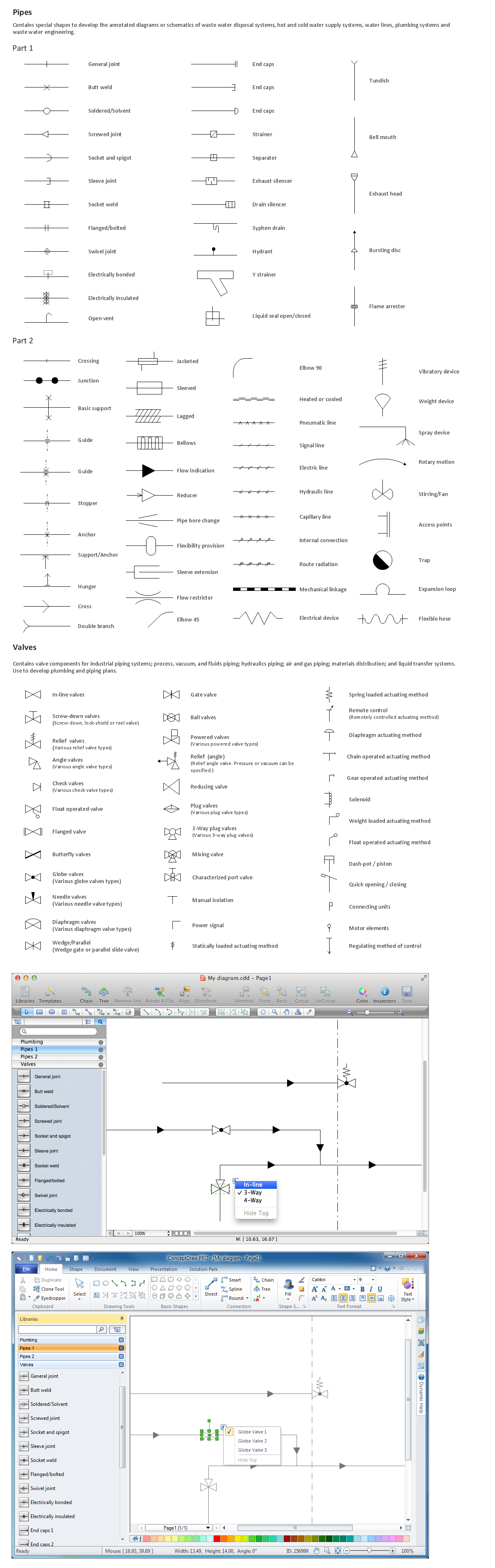
ConceptDraw is a good means of visualization of information of any kind as it features powerful graphic capabilities. Thus, on ConceptDraw graphic kernel the rest products of the line have been built, they are: ConceptDraw PROJECT, ConceptDraw MINDMAP . The powerful graphic kernel (2D-graphics) is supported by a number of open formats for data presentation (including XML). To this add flexibility of data processing connected with the scripting language ConceptDraw Basic. And also flexibility in parameterization of shapes provided by the whole shape parameter table (it is available for editing even right from the program's interface). So in the end it becomes clear that visualization of information in ConceptDraw is a good idea.

Benefits:

  • a number of templates and libraries with ready-to-use shapes
  • powerful graphic capabilities (2D-graphics)
  • scripting language ConceptDraw Basic
  • possibility to use external shared libraries
  • XML support
  • support of ODBC-compatible databases
  • multilateral parametrization of shapes
  • cross-platform (Mac, PC)

There are two approaches to interaction with ConceptDraw at visualization.

  • By an arbitrary, attached to no specific program, method you can save your data in one of the open ConceptDraw formats, leaving visualization and further processing to ConceptDraw.
  • In case 2 ConceptDraw Basic handles a part or the whole cycle (formation-reading-visualization of data).

The first approach is convenient for sparing you as a developer the necessity of writing the code to generate data in one specific system. You can choose the most convenient or the most familiar environment for your task. As ConceptDraw "reads" four open text formats (XML for ConceptDraw and XML for Visio), the situation is possible, if you do not have to write the code by just using some commercial program's export capabilities. For example, you prefer to get your data ready in MS Visio. In any case, the variety of open formats allows to choose the most suitable one for task: from Outline, good entirely for presentation of hierarchies (but the simplest and the briefest one) to ConceptDraw-document XML, which reflects any peculiarities. A third-party program has an opportunity of presenting its data by means of ConceptDraw providing the user with rich possibilities for their further processing (print, scaling, export to other formats, any corrections etc.).

With the appearance of such a tool as ConceptDraw Basic, a closer integration of your programs with ConceptDraw became possible. They can be implemented as scripts and run directly in the ConceptDraw environment. This fact cancels all restrictions dealing with the final number of formats read by the program. The scripting language has its own quite broad capabilities, including interface for interaction with ODBC-compatible databases. Besides, its capabilities can be enhanced on the expense of using the external modules (of shared libraries), created by other applications.

Let us consider several instances of visualization which may turn attractive to a developer of internet solutions.

In the package of ConceptDraw Professional Web Site Map Wizard is included. It builds a site map with the specified depth level or with no consideration of the depth, but within the domain name. It results in generation of the site map. It gives the user an opportunity to arbitrarily change the generated map (add or remove elements, change their sequence or depth, change the text, type and parameters etc.), export the map to other popular formats, it provides a number of opportunities for changing the document appearance (scaling, changing of colors, fonts and styles) and, of course, full-color print. An additional convenience is that ConceptDraw allows to send a link to the web-browser for viewing the document on this link in the browser window. Thus, the information output has been considerably simplified and functionality of the wizard considerably extended.

Internet solutions with ConceptDraw DIAGRAM *

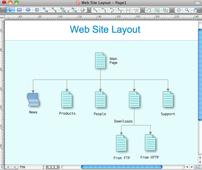
As the result of the work of the wizard appears the menu item for solving the reverse task. It builds up the site frame by the map. The map, used at building, can be generated by the same master. With the help of ConceptDraw the user can independently create a map of any complexity by using the wizard library objects, as well as arbitrary shapes. Also ConceptDraw allows to make all necessary changes to the map made on the existing sites.

The conception of using ConceptDraw and open formats by the programs that work with Internet can be used for displaying any data and any structure in Internet. You can build a map of a computer network, a domain map etc. And if regard Internet as the total of necessary information and spam, you can create a solution to search Internet for the given information and build the site map to meet your requirements. Then, with the help of ConceptDraw you can look through the map, selectively view your files, remove the sites from your map that do not answer your expectations, and modify your map in an arbitrary way.

Knowing HTML, you can write a solution to analyze web-documents by tags and display the results in ConceptDraw. The reverse task in its elementary shape is, basically, solved by ConceptDraw. But if for some specific purpose applied you need another variant of the final HTML-file, another solution could create an HTML document on the data in some other open format, generated with the help of ConceptDraw. Then, the process of web-page creation will turn easy and visual when constructing a ConceptDraw document.

The development of XML technology and the appearance of new browsers that support XML, lead to gradual displacement of HTML and setting XML as a de facto standard. XML support in ConceptDraw will allow you get your documents ready to be published in Internet in most effective way, and will considerably extend opportunities of the programs that use ConceptDraw as the means of visualization of their data.

ConceptDraw can be used both as a means of visualization and further processing of information not only by programs working with Internet, but also in any other field: network, database, analysis of a file system, analysis of any schemes etc.


TEN RELATED HOW TO's:
In case you need to make a plan for your own future hotel or to do it for someone else, then you can always find the way to make such template very quickly and to have a very good looking result in the end. Whichever type of the hotels you want to illustrate in a way of a floor plan, you can always do it with ConceptDraw DIAGRAM drawing application.Hotel Plan
Picture: Hotel Plan. Hotel Plan Examples
Related Solution:
Describing the way data flows through an information system might become a subject of a study. One of the kinds on a data flow diagram is called Gane Sarson Diagram after its authors, and it slightly differs from other notations. Process symbols in this notation are depicted as rounded rectangles connected with arrows representing data flows. This is a sample of data flow diagram. It demonstrates utilization of the Gane-Sarson notation for making DFD on the example of an online appointment system of the Health Centre. This sample is used the vector objects library of Gane-Sarson DFD notation supplied by the ConceptDraw solution for data flow diagramming. It contains all symbols of the Gane-Sarson notation including connectors, jumps, and processes. This solution can be successfully utilized to generate DFDs for business documentation, and presentations.Gane Sarson Diagram
Picture: Gane Sarson Diagram
Nodes of any computer network are somehow organized in a hierarchy or a layout. Some of the common layouts like star network topology are more reliable and some like ring topology withstand high loads better. It is also important to distinguish logical topologies from physical. This diagram represents a typical view of the star network topology. The star network topology is one of the most frequently used network topologies in the majority of office and home networks. It is very popular because of its low cost and the easy maintenance. The plus of the star network topology is that if one computer on the local network is downed, this means that only the failed computer can not send or receive data. The other part of the network works normally. The minus of using star network topology is that all computers are connected to a single point-switch, or hub. Thus, if this equipment goes down, the whole local network comes down.Star Network Topology *
Picture: Star Network Topology
Related Solution:
Interior design is an art of planning and coordinating the space in a building or on a floor to produce a charming and convenient environment for the client. You can ask professionals for help, or you can create floor plans easily with ConceptDraw DIAGRAM , using diverse libraries or altering numerous templates. You don’t need no formal training anymore to be a designer, isn’t it great? Using a ConceptDraw DIAGRAM floor plan software makes depicting of home or office layout ideas a simple task. It does not require special skills to make detailed and scaled floor plans. Adding furniture to design interior is also a breeze. You can draw and furnish your floor plans with a floor plan software. Moreover, using software for floor planning you gain an opportunity to share your plans and high-resolution images of your designs with clients or stakeholders.Create Floor Plans Easily with ConceptDraw DIAGRAM
Picture:
Create Floor Plans Easily
with ConceptDraw DIAGRAM Floor Design Software
Related Solution:
ConceptDraw DIAGRAM diagramming and vector drawing software extended with Gym and Spa Area Plans solution from Building Plans area of ConceptDraw Solution Park contains a set of examples, templates and design elements libraries for drawing Gym Workout Plan, Gym Floor Plan, Gym Layout Plan, Spa Floor Plan, Fitness Plan, etc.Gym Workout Plan *
Picture: Gym Workout Plan
Related Solution:
AWS →
The AWS diagrams are convenient way for explaining the work of Amazon Web Services. ConceptDraw DIAGRAM diagramming and vector drawing software offers the AWS Architecture Diagrams Solution from the Computer and Networks Area for fast and easy creating the AWS diagrams of any complexity.AWS *
Picture: AWS
Related Solution:
ConceptDraw DIAGRAM diagramming and vector drawing software as a sequence diagram tool provides the Rapid UML Solution from the Software Development Area that contains the UML Sequence library.Sequence Diagram Tool *
Picture: Sequence Diagram Tool
Related Solution:
Social media is a popular view of mass communication which allows people, companies and organizations create, share, discover, modify, access, comment, discuss and exchange information through the Internet. Social Media Response solution for ConceptDraw DIAGRAM provides collection of 10 libraries with diversity of predesigned vector social media flowchart symbols for fast and easy creating interactive Social Media Flowcharts, Response Charts and Action Mind Maps.Social Media Flowchart Symbols *
Picture: Social Media Flowchart Symbols
Related Solution:
Today, we can’t imagine our lives without daily data exchange. To call a set of devices that can be connected with each other a computer network, we must be sure that these devices support appropriate protocols to transfer data. A network consisting of personal devices is private, and global computer networks, for example, Internet, connects network nodes worldwide. This diagram represents a computer telecommunication network. The network depicted on the current diagram is featured with networked communication devices that provide data exchange through Internet. The network interconnections and connections between Internet nodes are settled using the cable media and wireless media. The nodes are the network workstations (terminals). and host computers. This network diagram was drawn with ConceptDraw DIAGRAM and its Computer and Networks Diagrams solution.Computer Network. <br>Computer and Network Examples *
Picture: Computer Network. Computer and Network Examples
Related Solution:
In general, you can use any icons to represent network equipment on a diagram. However, there are some icons, for instance, Cisco icons, shapes, stencils and symbols, that are recognizable worldwide. Using those icons you can create Cisco network topology diagrams in minutes and share them anywhere. The icons depicting Cisco network equipment are recognized and generally applied as standard images for designing network diagrams. They are free to used , but can not be reworked. Cisco network diagrams are created to depict how signals processed on the network equipment and end-user computers and how data transfer through LAN or WLAN between nodes. The vector graphic library of ConceptDraw CISCO Network Diagrams solution includes about 90 icons of Cisco network equipment for designing computer network diagrams with ConceptDraw DIAGRAM.Cisco Network Topology. <br>Cisco icons, shapes, stencils and symbols *
Picture: Cisco Network Topology. Cisco icons, shapes, stencils and symbols
Related Solution:
ConceptDraw
DIAGRAM 18