Interactive Voice Response Network Diagram


Network Diagramming Software for Design IVR Network Diagrams
")
Network Diagram Software Logical Network

Network Diagram Software IVR Balance Recharge Diagram

Design Element: IVR for Network Diagrams
")

 Computer and Networks Area
The solutions from Computer and Networks Area of ConceptDraw Solution Park collect samples, templates and vector stencils libraries for drawing computer and network diagrams, schemes and technical drawings.
Network Diagram Software Logical Network Diagram

"Network topology is the arrangement of the various elements (links, nodes, etc.) of a computer network. Essentially, it is the topological structure of a network, and may be depicted physically or logically. Physical topology refers to the placement of the network's various components, including device location and cable installation, while logical topology shows how data flows within a network, regardless of its physical design. Distances between nodes, physical interconnections, transmission rates, and/ or signal types may differ between two networks, yet their topologies may be identical. The study of network topology recognizes eight basic topologies: Point-to-point, Bus, Star, Ring or circular, Mesh, Tree, Hybrid, Daisy chain." [Network topology. Wikipedia]
The computer network topologies diagram example was created using the ConceptDraw PRO diagramming and vector drawing software extended with the Computer and Networks solution from the Computer and Networks area of ConceptDraw Solution Park.
The computer network topologies diagram example was created using the ConceptDraw PRO diagramming and vector drawing software extended with the Computer and Networks solution from the Computer and Networks area of ConceptDraw Solution Park.
Network topologies

Active Directory Domain Services

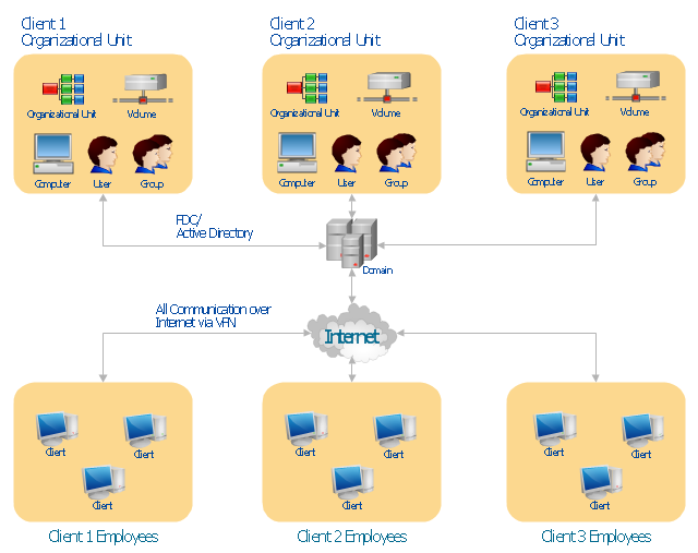
"Microsoft Windows 2000 Server introduces Active Directory to replace domain functionality. Active Directory will continue to get the job done, but in a much more efficient way. Active Directory can be replicated between multiple domain controllers, so no single system is critical. In this way, the crucial data stored within Active Directory is both redundant and load-balanced.
A directory, in the most generic sense, is a comprehensive listing of objects. A phone book is a type of directory that stores information about people, businesses, and government organizations. Phone books typically record names, addresses, and phone numbers. Active Directory is similar to a phone book in several ways, and it is far more flexible. Active Directory will store information about organizations, sites, systems, users, shares, and just about any other network object that you can imagine. Not all objects are as similar to each other as those stored in the phone book, so Active Directory includes the ability to record different types of information about different objects." [technet.microsoft.com/ en-us/ library/ bb742424.aspx]
The AD diagram example "Active Directory structure diagram" was created using the ConceptDraw PRO diagramming and vector drawing software extended with the Active Directory Diagrams solution from the Computer and Networks area of ConceptDraw Solution Park.
Active Directory network diagram
"... logical topology shows how data flows within a network, regardless of its physical design. ...
The logical topology in contrast, is the way that the signals act on the network media, or the way that the data passes through the network from one device to the next without regard to the physical interconnection of the devices. A network's logical topology is not necessarily the same as its physical topology." [Network topology. Wikipedia]
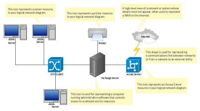
The logical network diagram template for the ConceptDraw PRO diagramming and vector drawing software is included in the Computer and Networks solution from the Computer and Networks area of ConceptDraw Solution Park.
The logical topology in contrast, is the way that the signals act on the network media, or the way that the data passes through the network from one device to the next without regard to the physical interconnection of the devices. A network's logical topology is not necessarily the same as its physical topology." [Network topology. Wikipedia]
The logical network diagram template for the ConceptDraw PRO diagramming and vector drawing software is included in the Computer and Networks solution from the Computer and Networks area of ConceptDraw Solution Park.
Logical network diagram template
 Computer Network Diagrams
Computer Network Diagrams solution extends ConceptDraw PRO software with samples, templates and libraries of vector icons and objects of computer network devices and network components to help you create professional-looking Computer Network Diagrams, to plan simple home networks and complex computer network configurations for large buildings, to represent their schemes in a comprehensible graphical view, to document computer networks configurations, to depict the interactions between network's components, the used protocols and topologies, to represent physical and logical network structures, to compare visually different topologies and to depict their combinations, to represent in details the network structure with help of schemes, to study and analyze the network configurations, to communicate effectively to engineers, stakeholders and end-users, to track network working and troubleshoot, if necessary.
- UML Composite Structure Diagram
- Active Directory structure diagram | Active Directory Domain ...
- Network Architecture | Computer and Networks Area | Network ...
- UML Composite Structure Diagram | Network Architecture | Network ...
- Network Architecture | Computer and Networks | Fishbone Diagram |
- Network diagrams with ConceptDraw PRO | Interactive Voice ...
- Cisco Network Templates | Computer network diagram template ...
- How to Draw a Computer Network Diagrams | Engineering ...
- How to Draw a Computer Network Diagrams | Design Element: IVR ...
- Network Architecture | Network diagrams with ConceptDraw PRO ...
- Data structure diagram with ConceptDraw PRO | Organizational ...
- Network Printer | Computer network diagram | Logical network ...
- Network Diagram Software Logical Network Diagram
- Network Diagram Software Physical Network Diagram | Network ...
- Active Directory diagrams with ConceptDraw PRO
- UML Composite Structure Diagram | Rapid UML | Technical ...
- How to Draw a Computer Network Diagrams | Network ...
- Active Directory structure diagram
- How to Draw a Computer Network Diagrams | ConceptDraw PRO ...
- Network Printer | Computer network diagram | Network diagrams ...