Electrical Symbols, Electrical Diagram Symbols

CAD Drawing Software for Making Mechanic Diagram and Electrical Diagram Architectural Designs


Electrical Symbols — Terminals and Connectors

Interior Design. Piping Plan — Design Elements

Electrical Engineering

Electrical and Telecom Plan Software

Cisco Switches and Hubs. Cisco icons, shapes, stencils and symbols

 Electrical Engineering
This solution extends ConceptDraw DIAGRAM.9.5 (or later) with electrical engineering samples, electrical schematic symbols, electrical diagram symbols, templates and libraries of design elements, to help you design electrical schematics, digital and analog
Office Floor Plans

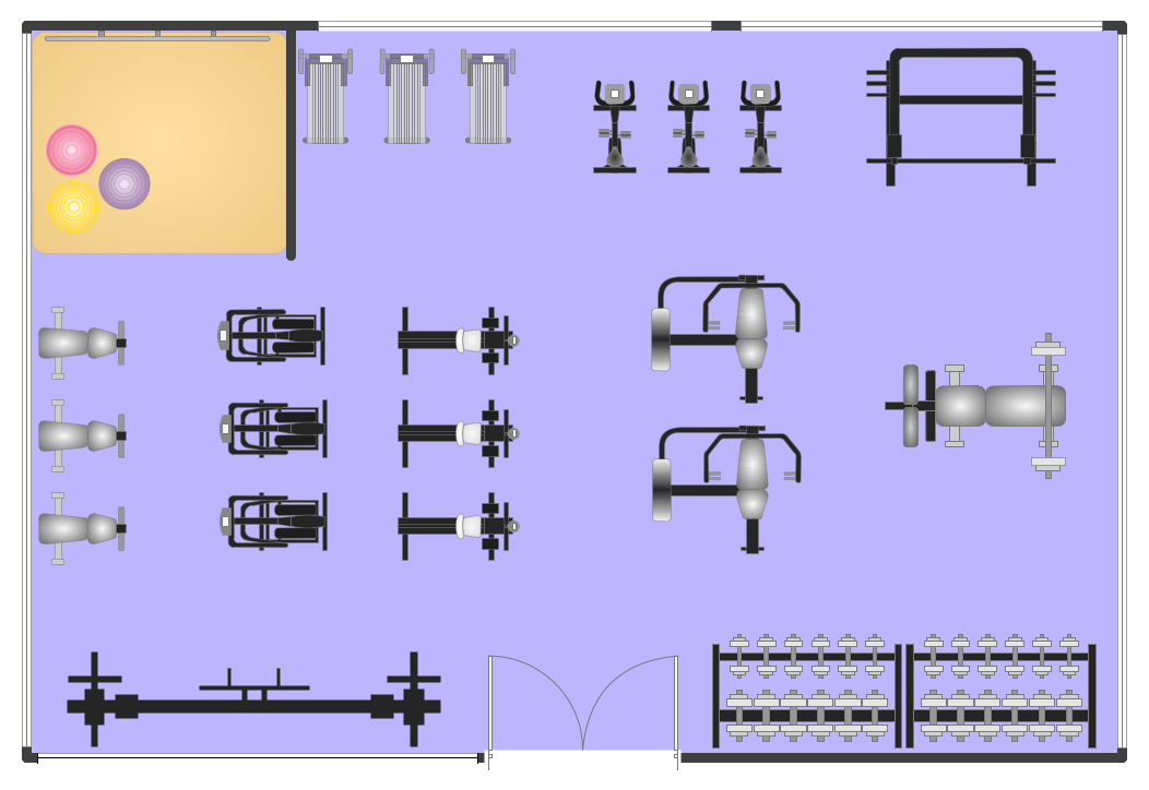
Fitness Plans
- Drawing Of Welding Joints
- Electrical Symbols , Electrical Diagram Symbols | How To use House ...
- Electrical Symbols , Electrical Diagram Symbols | How To use House ...
- Electrical Symbols , Electrical Diagram Symbols | How To use House ...
- How To use House Electrical Plan Software | Electrical Symbols ...
- Electrical Symbols — Terminals and Connectors | Electrical Symbols ...
- About Welded Joint In Engineering Drawing
- How To use House Electrical Plan Software | Home Electrical Plan ...
- Electrical Symbols , Electrical Diagram Symbols | Electrical Symbols ...
- How To use House Electrical Plan Software | Electrical Symbols ...