UML Diagrams with ConceptDraw DIAGRAM

UML Diagram

UML Tool & UML Diagram Examples

Diagramming Software for Design UML Activity Diagrams


Cisco Network Diagram Software

Entity-Relationship Diagram (ERD) with ConceptDraw DIAGRAM


UML Diagram Types List

Diagramming Software for Design UML Collaboration Diagrams

Create UML Diagram
Cisco IBM. Cisco icons, shapes, stencils and symbols

- How To Create Class Diagram In Visio
- UML Diagram Visio | UML Deployment Diagram. Diagramming ...
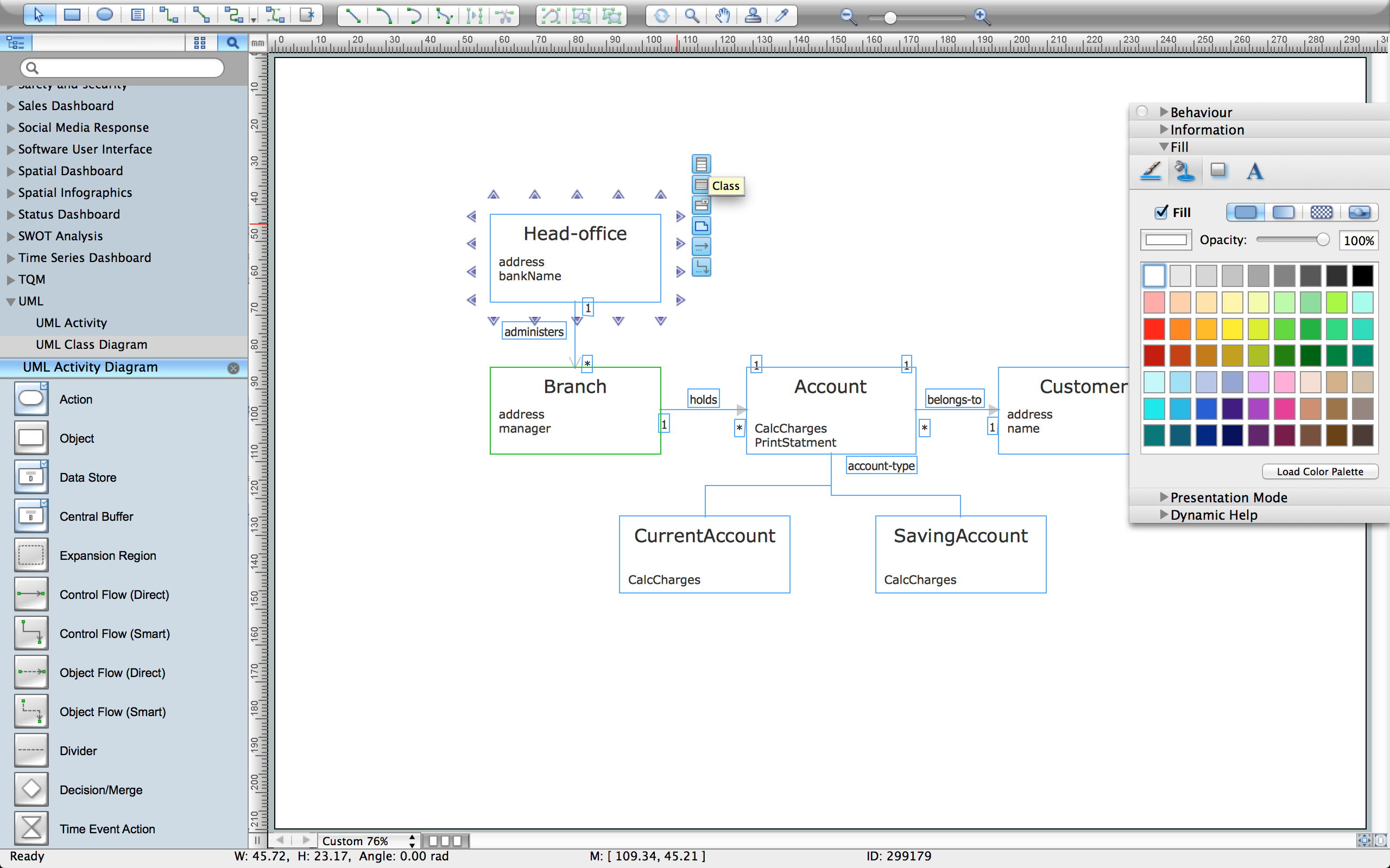
- Banking System Uml Diagram Free Download
- ATM UML Diagrams | Rapid UML | Free Download Bank System Uml
- ATM UML Diagrams
- Bank Sequence Diagram | ATM UML Diagrams | How to Create a ...
- ATM UML Diagrams | Bank System | Banking System | Multi Banking ...
- UML Diagram of Parking | UML Use Case Diagram Example Social ...
- UML Deployment Diagram . Diagramming Software for Design UML ...
- UML Block Diagram | UML Diagram Types List | UML Diagram ...