Electrical Symbols — Inductors

Electrical Symbols — Transformers and Windings
Electrical Symbols, Electrical Diagram Symbols

Electrical Drawing Software and Electrical Symbols

Electrical Diagram

Electrical Symbols — Lamps, Acoustics, Readouts

Electrical Symbols — MOSFET

Electrical Symbols — Analog and Digital Logic

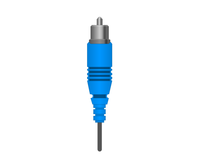
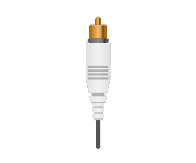
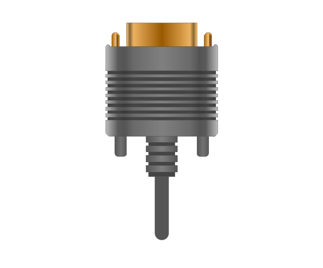
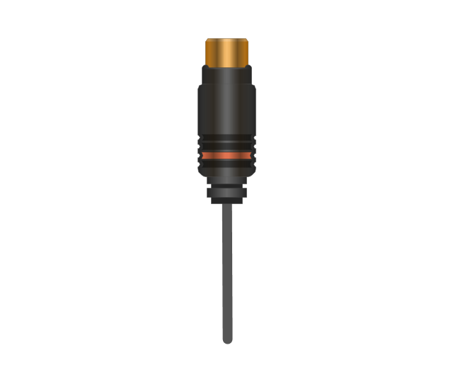
The vector stencils library "Audio and video connectors" contains 94 symbols of audio and video connectors and device silhouettes.
Use these jacks and plugs clipart icons for drawing hook up diagrams in the ConceptDraw PRO diagramming and vector drawing software extended with the Audio and Video Connectors solution from the Engineering area of ConceptDraw Solution Park.
www.conceptdraw.com/ solution-park/ engineering-audio-video-connectors
Device 1

Device 2

TV

Cable, thin

Cable, thick

Device 1, half part

Device 2, half part

TRS plug, purple
TRS plug, brown
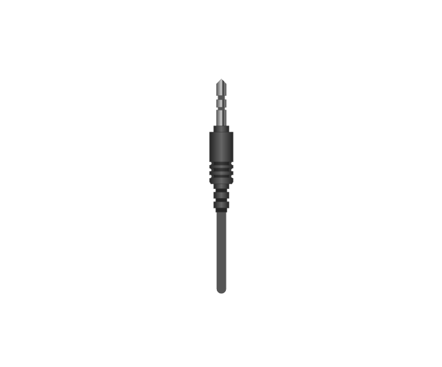
TRS plug, black

TRS plug, gray
TRS plug, blue
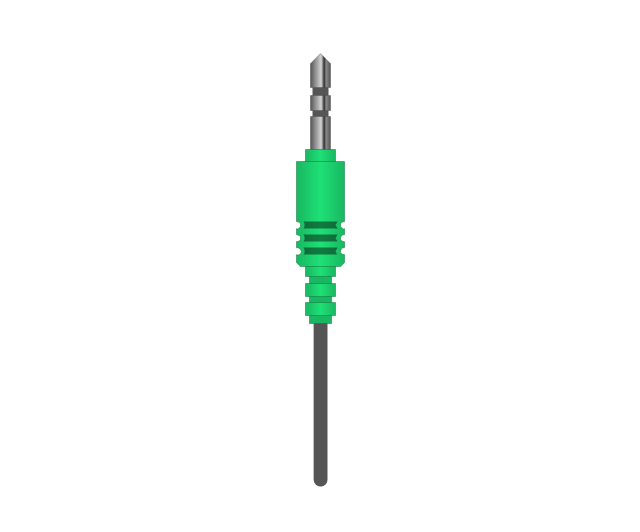
TRS plug, green
TRS jack, purple

TRS jack, brown

TRS jack, black

TRS jack, gray

TRS jack, blue

TRS jack, green

TRS plug, micro-jack
TRS, micro-jack

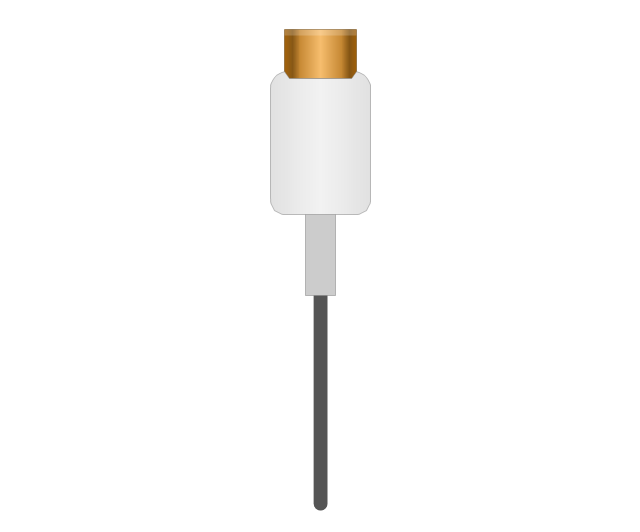
Headphone Mini Jack Cable
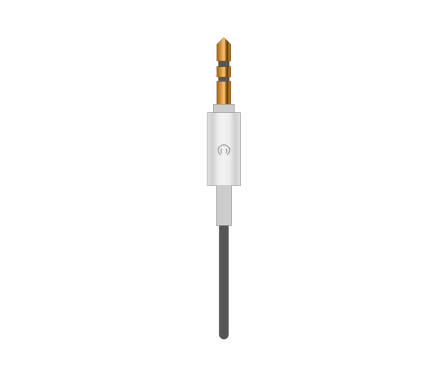
Headphone Mini Jack

Microphone Mini Jack Cable
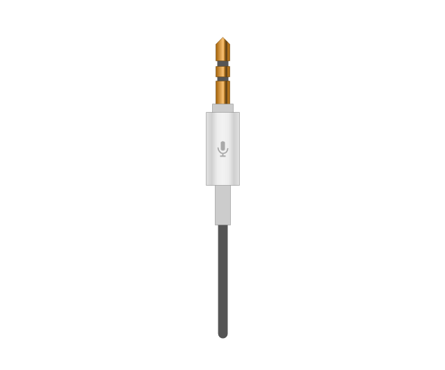
Microphone Mini Jack

XLR female Neutrik
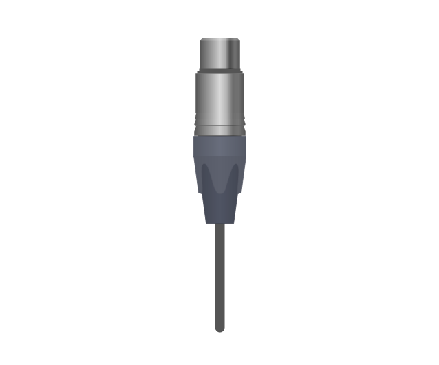
XLR female Neutrik

TOSLINK Optical Audio Cable, blue
TOSLINK Optical Audio Cable
TOSLINK Optical jack

TOSLINK Optical jack, blue

DVI plug
DVI-I (Single Link) jack
-jack-audio-and-video-connectors---vector-stencils-library.png--diagram-flowchart-example.png)
DVI-I (Dual Link) jack
-jack-audio-and-video-connectors---vector-stencils-library.png--diagram-flowchart-example.png)
DVI-D (Single Link) jack
-jack-audio-and-video-connectors---vector-stencils-library.png--diagram-flowchart-example.png)
DVI-D (Dual Link) jack
-jack-audio-and-video-connectors---vector-stencils-library.png--diagram-flowchart-example.png)
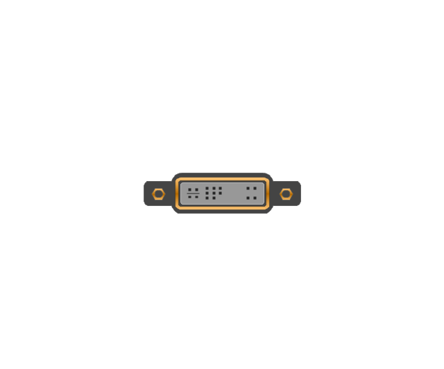
DVI-A Port
DVI-I (Single Link)
-audio-and-video-connectors---vector-stencils-library.png--diagram-flowchart-example.png)
DVI-I (Dual Link)
-audio-and-video-connectors---vector-stencils-library.png--diagram-flowchart-example.png)
DVI-D (Single Link)
-audio-and-video-connectors---vector-stencils-library.png--diagram-flowchart-example.png)
DVI-D (Dual Link)
-audio-and-video-connectors---vector-stencils-library.png--diagram-flowchart-example.png)
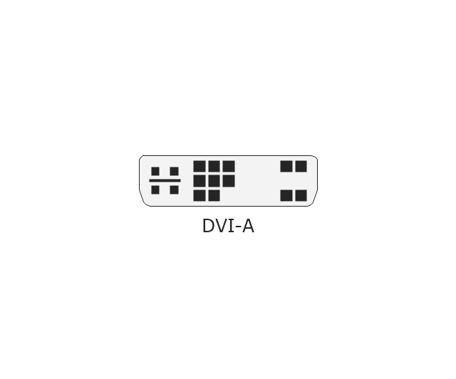
DVI-A
Mini DVI jack
Mini DVI plug
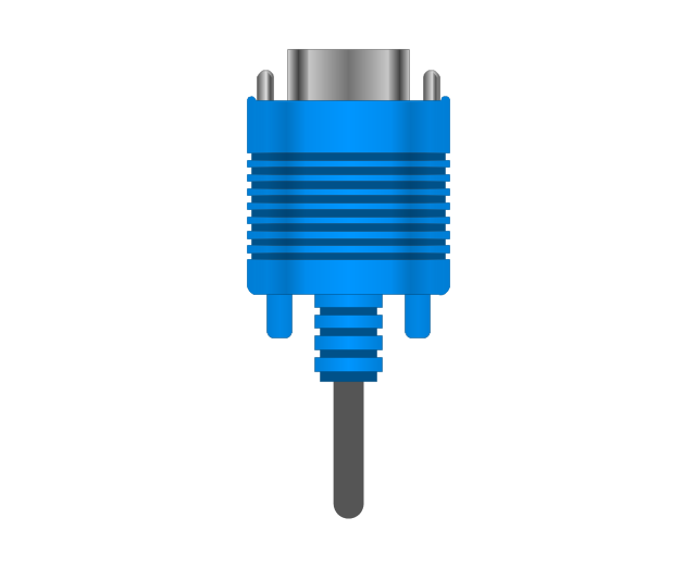
VGA plug
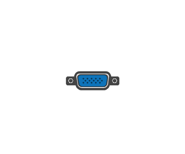
VGA jack
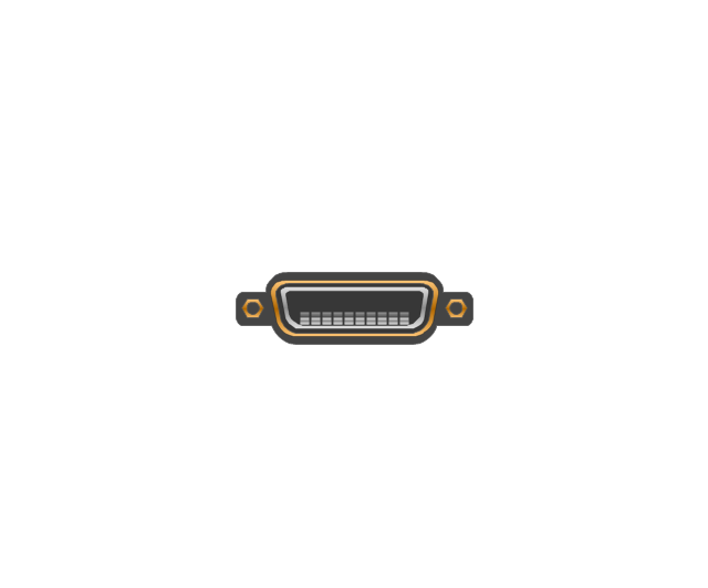
DFP jack
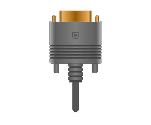
DFP plug
S-Video plug
S-Video IN

S-Video OUT

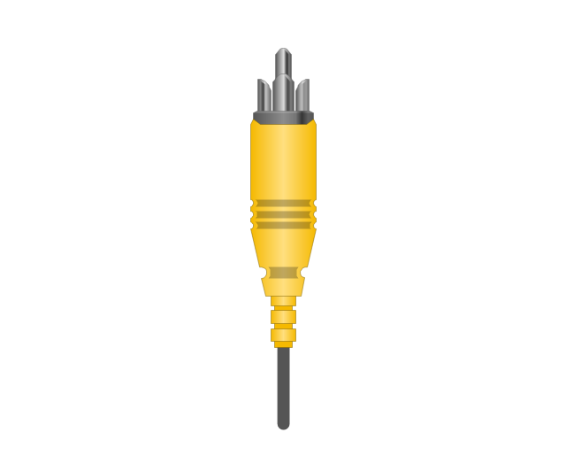
RCA, yellow

RCA, yellow
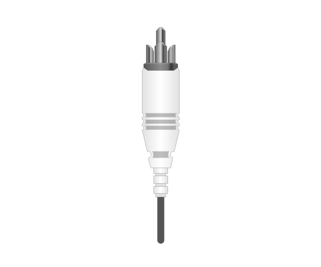
RCA, white

RCA, white
RCA, red

RCA, red

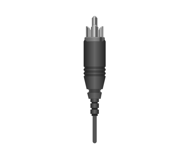
RCA, black

RCA, black
RCA, green

RCA, green
RCA, blue

RCA, blue
RCA, gray

RCA, gray
RCA, brown

RCA, brown
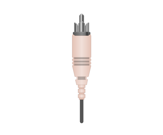
RCA, tan

RCA, tan
RCA, purple
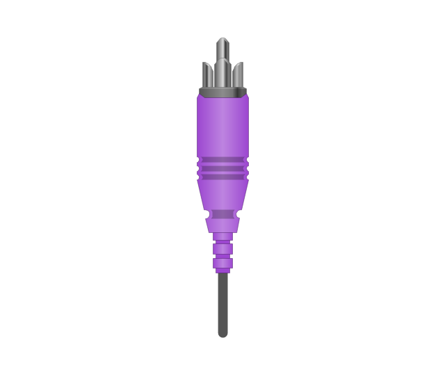
RCA, purple

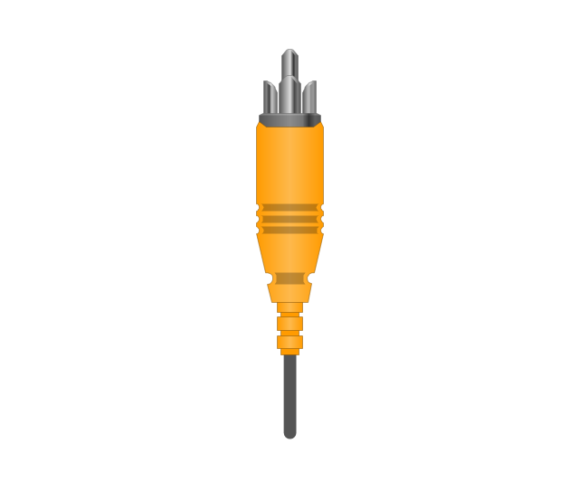
RCA, orange

RCA, orange
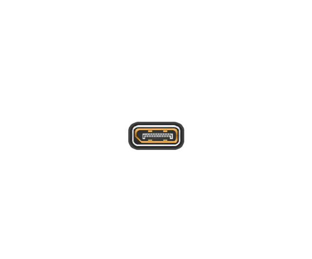
Display Port socket
Display Port plug
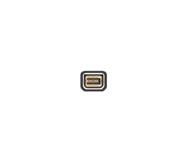
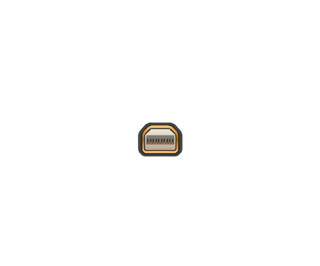
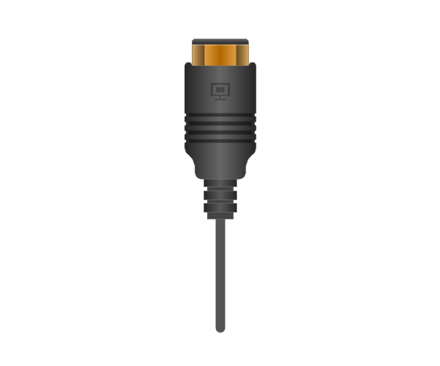
Mini Display port socket
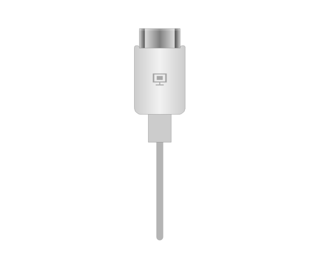
Mini Display port socket, white

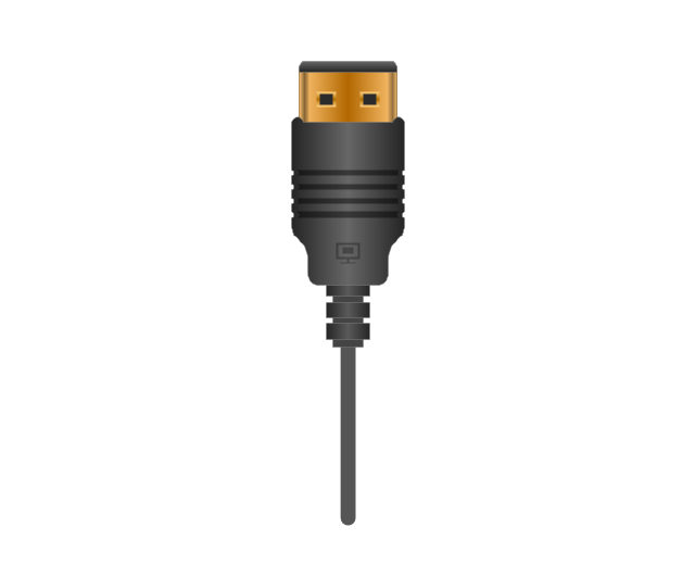
Mini Display port plug
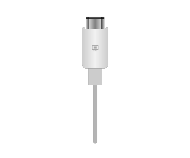
Mini Display port plug, white
HDMI jack

HDMI plug
HDMI plug, white
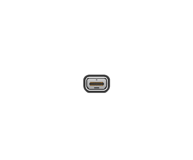
Thunderbolt jack
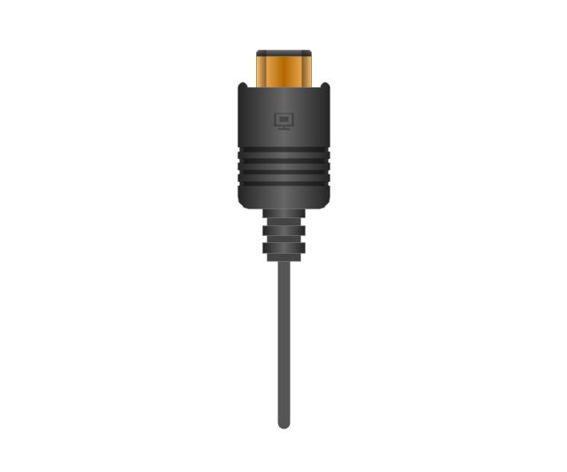
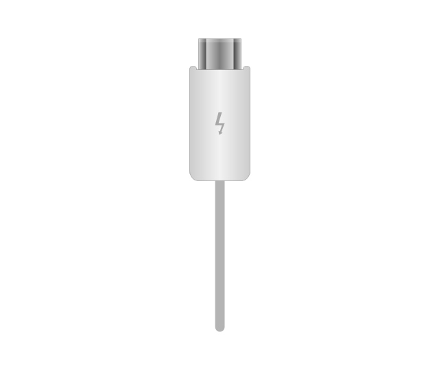
Thunderbolt plug
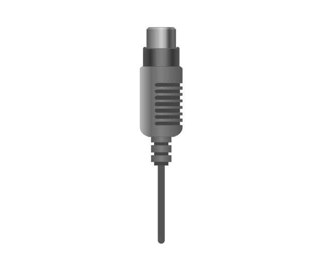
Coaxial TV plug
Coaxial TV jack

F connector jack

F connector plug
XLR male Neutrik

XLR male Neutrik
TS plug
TS jack

MIDI

MIDI
- Design elements - Inductors | Design elements - Electrical circuits ...
- Electrical Symbols , Electrical Diagram Symbols | Electrical Symbols ...
- Electrical Symbols , Electrical Diagram Symbols | How To use House ...
- Symbol For Control Transformer
- Electrical Symbols , Electrical Diagram Symbols | Mechanical ...
- Flowchart Components | Electrical Symbols , Electrical Diagram ...
- Mechanical Drawing Symbols | Process Flow Diagram Symbols ...
- Solar System Symbols | Sun Solar System | Sketching Software ...
- Mechanical Drawing Software | Mechanical Drawing Symbols ...
- Electrical Symbols — Lamps, Acoustics, Readouts | Lamps ...