How To use House Electrical Plan Software


Local area network (LAN). Computer and Network Examples
. Computer and Network Examples")

Network Diagram Software LAN Network Diagrams & Diagrams for LAN Physical Office Network Diagrams

Electrical Symbols, Electrical Diagram Symbols

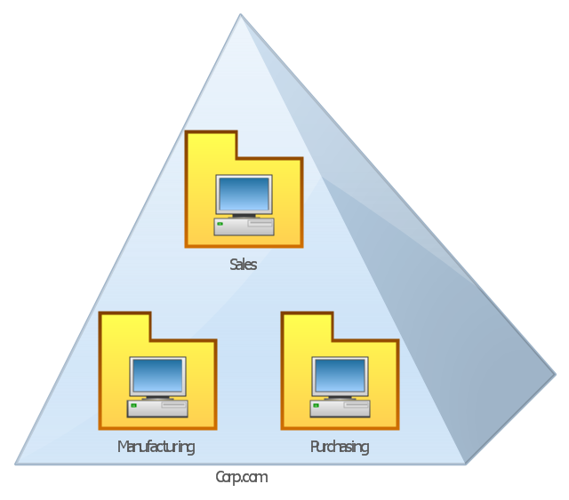
This AD diagram example was redesigned from the picture "Single root domain with a structured OU model" from the book "Active Directory for Dummies".
"A domain is the cornerstone that you lay whenever you create trees and forests. Regardless of whether you design a tree or a forest, the starting point is always the root domain. The root domain is the first domain that you create in your AD structure, and it sits at the top of your diagram.
The root domain of your tree, similar to any other domain, is a grouping of
resources built on the following components:
(1) Domain controllers.
(2) Security policies. ...
For many small and medium-sized companies, a single root domain with a
structured OU (organizational unit) model... provides sufficient flexibility for an AD tree. ...
However, larger companies, companies with complex organization charts, and
companies with multiple sites often find that a single domain isn’t suitable." [Steve Clines and Marcia Loughry, Active Directory® For Dummies®, 2nd Edition. 2008]
The Active Directory diagram example "Single root domain with a structured OU model" was created using the ConceptDraw PRO diagramming and vector drawing software extended with the Active Directory Diagrams solution from the Computer and Networks area of ConceptDraw Solution Park.
Active Directory network diagram
 Network Layout Floor Plans
Network Layout Floor Plans solution extends ConceptDraw PRO software functionality with powerful tools for quick and efficient documentation the network equipment and displaying its location on the professionally designed Network Layout Floor Plans. Never before creation of Network Layout Floor Plans, Network Communication Plans, Network Topologies Plans and Network Topology Maps was not so easy, convenient and fast as with predesigned templates, samples, examples and comprehensive set of vector design elements included to the Network Layout Floor Plans solution. All listed types of plans will be a good support for the future correct cabling and installation of network equipment.
Hotel Network Topology Diagram. Hotel Guesthouse WiFi Network

Point to Point Network Topology

Bus Network Topology

Emergency Plan


- Single Stroke Calling Bell Diagram Com
- Lay Out Calling Bell Symbol
- Single Line Diagram Electriccal Network Android
- Single Stroke Calling Bell Diagram
- Diagram Of Single Stroke Calling Bell
- Floor Plan Of A Restaurant With Single Line Diagram
- Single Line Diagram Of A Hotel
- Single Stroke Calling Bell Circuit Diagram
- Single Stoke Calling Bell
- Diagarm Single Stroke Calling Bell Symbol