UML State Machine Diagram.Design Elements

This example was redesigned from the Wikimedia Commons file: UML state diagram.png.
[commons.wikimedia.org/ wiki/ File:UML_ state_ diagram.png]
This file is licensed under the Creative Commons Attribution-Share Alike 3.0 Unported license. [creativecommons.org/ licenses/ by-sa/ 3.0/ deed.en]
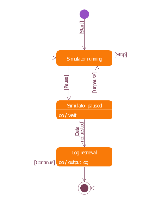
"The StateMachine package defines a set of concepts that can be used for modeling discrete behavior through finite state transition systems. The state machine represents behavior as the state history of an object in terms of its transitions and states. The activities that are invoked during the transition, entry, and exit of the states are specified along with the associated event and guard conditions. Activities that are invoked while in the state are specified as “do Activities,” and can be either continuous or discrete. A composite state has nested states that can be sequential or concurrent.
The UML concept of protocol state machines is excluded from SysML to reduce the complexity of the language.
The standard UML state machine concept (called behavior state machines in UML) are thought to be sufficient for expressing protocols." [omg.org/ spec/ SysML/ 1.3/ PDF]
The example "State machine diagram" was drawn using the ConceptDraw PRO diagramming and vector drawing software extended with the SysML solution from the Software Development area of ConceptDraw Solution Park.
[commons.wikimedia.org/ wiki/ File:UML_ state_ diagram.png]
This file is licensed under the Creative Commons Attribution-Share Alike 3.0 Unported license. [creativecommons.org/ licenses/ by-sa/ 3.0/ deed.en]
"The StateMachine package defines a set of concepts that can be used for modeling discrete behavior through finite state transition systems. The state machine represents behavior as the state history of an object in terms of its transitions and states. The activities that are invoked during the transition, entry, and exit of the states are specified along with the associated event and guard conditions. Activities that are invoked while in the state are specified as “do Activities,” and can be either continuous or discrete. A composite state has nested states that can be sequential or concurrent.
The UML concept of protocol state machines is excluded from SysML to reduce the complexity of the language.
The standard UML state machine concept (called behavior state machines in UML) are thought to be sufficient for expressing protocols." [omg.org/ spec/ SysML/ 1.3/ PDF]
The example "State machine diagram" was drawn using the ConceptDraw PRO diagramming and vector drawing software extended with the SysML solution from the Software Development area of ConceptDraw Solution Park.
SysML state machine diagram
Booch OOD Diagram

State Diagram Example - Online Store

Diagramming Software for Design UML State Machine Diagrams


Software Diagram Examples and Templates

Finite State Machine

 IDEF Business Process Diagrams
Use the IDEF Business Process Diagrams solution to create effective database designs and object-oriented designs, following the integration definition methodology.
IDEF3 Standard

UML Class Diagram Generalization Example UML Diagrams

- Draw State Transition Diagram For Function Template
- UML state machine diagram - Template | Design elements - Bank ...
- Online Cab Management System Draw A State Transition Diagram
- Uml State Transition Examples
- UML state machine diagram - Template
- UML state machine diagram - Template | IDEF3 Standard | UML ...
- State Machine Diagram | UML State Machine Diagram .Design ...
- UML state machine diagram - Template | UML state machine ...
- State machine diagram | Design elements - Bank UML state ...
- IDEF3 Standard | State Transition Diagram Online