HelpDesk
How to Split a Complex Map to a Few Simple Maps

Electrical Symbols — IGFET

Electrical Symbols — MOSFET

Electrical Symbols — Transistors

Electrical Symbols — Semiconductor

 Management
This solution extends ConceptDraw PRO v9 and ConceptDraw MINDMAP v7 with Management Diagrams and Mind Maps (decision making, scheduling, thinking ideas, problem solving, business planning, company organizing, SWOT analysis, preparing and holding meetings
Personal area (PAN) networks. Computer and Network Examples
 networks. Computer and Network Examples")

 Floor Plans
Construction, repair and remodeling of the home, flat, office, or any other building or premise begins with the development of detailed building plan and floor plans. Correct and quick visualization of the building ideas is important for further construction of any building.
 Word Exchange
This solution extends ConceptDraw MINDMAP software with the ability to quickly create the framework for a future article or book, fill the structure with ideas, and use it to produce an MS Word document with just a simple click of the mouse.
The vector stencils library "Logic gate diagram" contains 17 element symbols for drawing the logic gate diagrams.
"To build a functionally complete logic system, relays, valves (vacuum tubes), or transistors can be used. The simplest family of logic gates using bipolar transistors is called resistor-transistor logic (RTL). Unlike simple diode logic gates (which do not have a gain element), RTL gates can be cascaded indefinitely to produce more complex logic functions. RTL gates were used in early integrated circuits. For higher speed and better density, the resistors used in RTL were replaced by diodes resulting in diode-transistor logic (DTL). Transistor-transistor logic (TTL) then supplanted DTL. As integrated circuits became more complex, bipolar transistors were replaced with smaller field-effect transistors (MOSFETs); see PMOS and NMOS. To reduce power consumption still further, most contemporary chip implementations of digital systems now use CMOS logic. CMOS uses complementary (both n-channel and p-channel) MOSFET devices to achieve a high speed with low power dissipation." [Logic gate. Wikipedia]
The symbols example "Design elements - Logic gate diagram" was drawn using the ConceptDraw PRO diagramming and vector drawing software extended with the Electrical Engineering solution from the Engineering area of ConceptDraw Solution Park.
Logic gate symbols

Flow chart Example. Warehouse Flowchart


"Basic Bunt Coverage ...
The next few posts will be related to bunt coverages. I will include a diagram, a description of the situation, and a position by position description of field responsibilities. Some of these coverages will be very standard." [coach5150.wordpress.com/ 2009/ 12/ 28/ basic-bunt-coverage-1/ ]
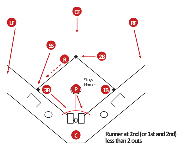
"Basic Bunt Coverage #2: Runner at 2nd.
Situation: Runner at 2nd base or runners at both 1st and 2nd. Less than 2 outs." [coach5150.wordpress.com/ 2010/ 01/ 01/ basic-bunt-coverage-2-runner-at-2nd/ ]
The baseball positions diagram example "Basic bunt coverage - Runner at 2nd" was created using the ConceptDraw PRO diagramming and vector drawing software extended with the Baseball solution from the Sport area of ConceptDraw Solution Park.
The next few posts will be related to bunt coverages. I will include a diagram, a description of the situation, and a position by position description of field responsibilities. Some of these coverages will be very standard." [coach5150.wordpress.com/ 2009/ 12/ 28/ basic-bunt-coverage-1/ ]
"Basic Bunt Coverage #2: Runner at 2nd.
Situation: Runner at 2nd base or runners at both 1st and 2nd. Less than 2 outs." [coach5150.wordpress.com/ 2010/ 01/ 01/ basic-bunt-coverage-2-runner-at-2nd/ ]
The baseball positions diagram example "Basic bunt coverage - Runner at 2nd" was created using the ConceptDraw PRO diagramming and vector drawing software extended with the Baseball solution from the Sport area of ConceptDraw Solution Park.
Baseball positions diagram
"Basic Bunt Coverage ...
The next few posts will be related to bunt coverages. I will include a diagram, a description of the situation, and a position by position description of field responsibilities. Some of these coverages will be very standard." [coach5150.wordpress.com/ 2009/ 12/ 28/ basic-bunt-coverage-1/ ]
"Basic Bunt Coverage #2: Runner at 2nd.
Situation: Runner at 2nd base or runners at both 1st and 2nd. Less than 2 outs." [coach5150.wordpress.com/ 2010/ 01/ 01/ basic-bunt-coverage-2-runner-at-2nd/ ]
The baseball positions diagram example "Basic bunt coverage - Runner at 2nd" was created using the ConceptDraw PRO diagramming and vector drawing software extended with the Baseball solution from the Sport area of ConceptDraw Solution Park.
Baseball positions diagram
- Amplifier - Circuit diagram | Design elements - Transistors | Simple ...
- How to Split a Complex Map to a Few Simple Maps | Note Exchange ...
- Chemical Plant Simple P And Id Diagram Sample
- How to Split a Complex Map to a Few Simple Maps | Management ...
- Crude Oil Distillation Unit P
- Marketing P
- Process P
- Symbol In P
- Floor Plans | Emergency Plan | Word Exchange | Floor P
- Simple Plant Layout In Template Of Multi Storage Building
- Floor Plans | Venn Diagram Examples for Problem Solving ...
- Design elements - Logic gate diagram | Valve Symbols On P
- Chemical Plant P And Id Diagram Sample
- Electrical Symbols — Transistors | Design elements - Transistors ...
- Electrical Symbols — MOSFET | Design elements - Transistors ...
- Electrical Symbols — Transistors | Electrical Symbols — MOSFET ...
- Electrical Symbols — VHF UHF SHF | Design elements - Transistors ...
- 4 P Diagram
- Electrical Symbols, Electrical Diagram Symbols | Electrical Symbols ...
- Electrical Symbols — MOSFET | Design elements - MOSFET ...