How To use House Electrical Plan Software


Electrical Symbols, Electrical Diagram Symbols

Electrical Symbols — Terminals and Connectors

Wiring Diagram Floor Software
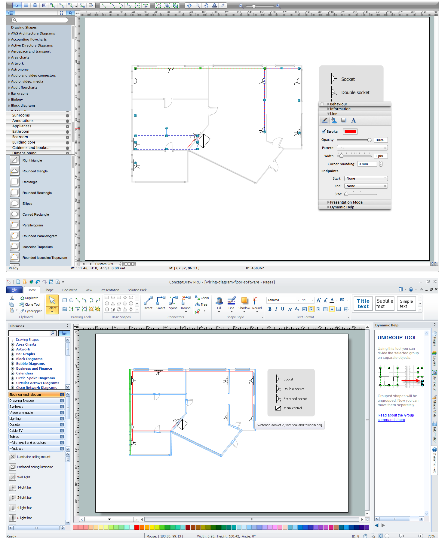
Home Electrical Plan

 Network Layout Floor Plans
Network Layout Floor Plans solution extends ConceptDraw DIAGRAM software functionality with powerful tools for quick and efficient documentation the network equipment and displaying its location on the professionally designed Network Layout Floor Plans. Never before creation of Network Layout Floor Plans, Network Communication Plans, Network Topologies Plans and Network Topology Maps was not so easy, convenient and fast as with predesigned templates, samples, examples and comprehensive set of vector design elements included to the Network Layout Floor Plans solution. All listed types of plans will be a good support for the future correct cabling and installation of network equipment.
How To Create Emergency Plans and Fire Evacuation

Wiring Diagrams with ConceptDraw DIAGRAM

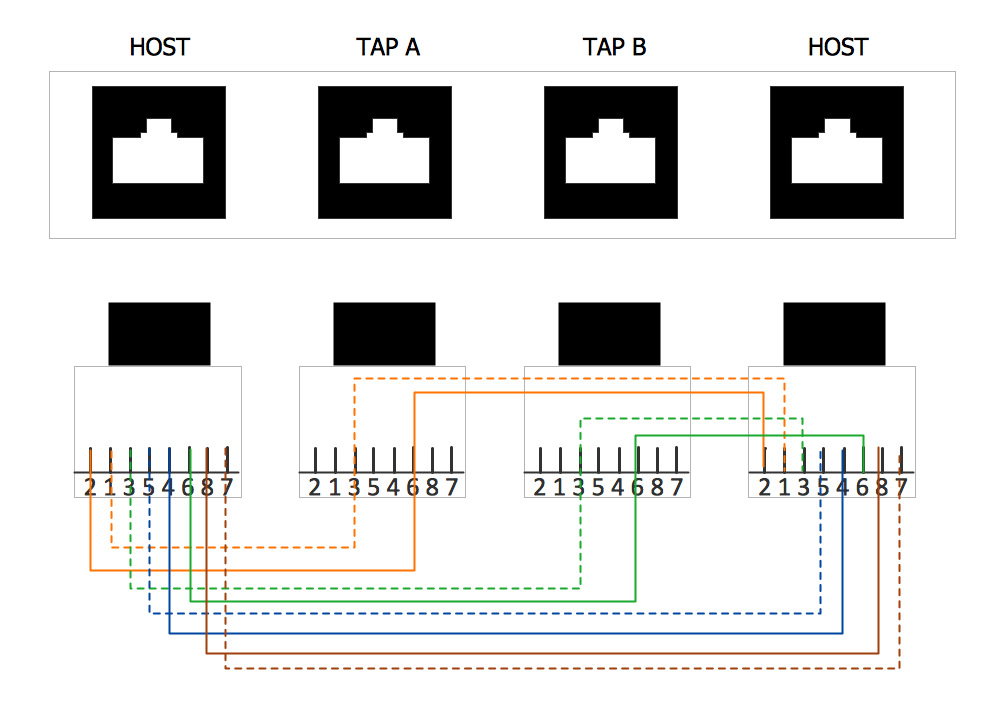
Network wiring cable. Computer and Network Examples


Network wiring. Computer and Network Examples
- Electrical Wiring Floor Plan Legend
- Cctv Legend Symbols
- What Is The Purpose Of A Legend On A Set Of Building Plans
- How To use House Electrical Plan Software | Home Electrical Plan ...
- Office Electrical Wiring Plan
- Floor Plan Legend Example
- Mechanical Drawing Symbols | Electrical Symbols, Electrical ...
- Reflected Ceiling Plan Lighting Symbols Legend
- How to Create a Residential Plumbing Plan | Plumbing and Piping ...
- A Pictorial Diagram For A Three Bedroom Flat With Legend