HelpDesk
How to Draw an Emergency Plan for Your Office
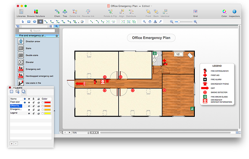
Emergency Floor Plan is important to supply an office staff with a visual safety solution. Emergency Floor Plan diagram presents a set of standard symbols used to depict fire safety, emergency, and associated information. Using clear and standard symbols on fire emergency plans delivers the coherence of collective actions , helps to avoid embarrassment, and improves communications in an emergent situation. The fire emergency symbols are intended for the general emergency and fire service, as well as for building plans ,engineering drawings and insurance diagrams. They can be used during fire extinguishing and evacuation operations, as well as training. It includes vector symbols for emergency management mapping, emergency evacuation diagrams and plans. You can use ConceptDraw PRO to make the fire evacuation plans for your office simple, accurate and easy-to-read.
 Network Layout Floor Plans
Network Layout Floor Plans solution extends ConceptDraw PRO software functionality with powerful tools for quick and efficient documentation the network equipment and displaying its location on the professionally designed Network Layout Floor Plans. Never before creation of Network Layout Floor Plans, Network Communication Plans, Network Topologies Plans and Network Topology Maps was not so easy, convenient and fast as with predesigned templates, samples, examples and comprehensive set of vector design elements included to the Network Layout Floor Plans solution. All listed types of plans will be a good support for the future correct cabling and installation of network equipment.
 Plumbing and Piping Plans
Plumbing and Piping Plans solution extends ConceptDraw PRO v10.2.2 software with samples, templates and libraries of pipes, plumbing, and valves design elements for developing of water and plumbing systems, and for drawing Plumbing plan, Piping plan, PVC Pipe plan, PVC Pipe furniture plan, Plumbing layout plan, Plumbing floor plan, Half pipe plans, Pipe bender plans.
HelpDesk
How to Draw a Pie Chart Using ConceptDraw PRO
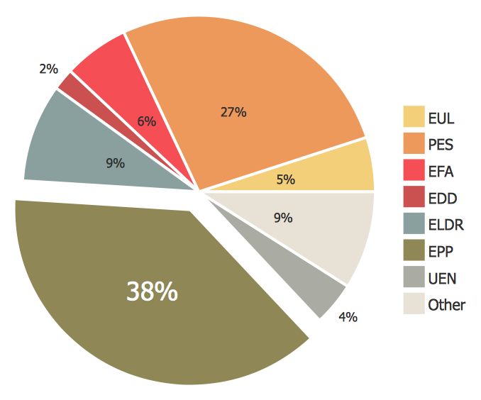
A pie chart represents data, in a clear and easy to read round (pie) form. A circular pie chart is divided into sections (slice). Each "slice" depicts the It reflects the proportion of each component in the whole "pie". This type of chart is most often used for the visualization of statistical data. That is why pie charts are widely used in marketing. As pie charts show proportional proportional parts of a whole, they are good for various visual comparisons. For example, it is difficult to imagine a more intuitive way to show segmentation and market share. ConceptDraw PRO allows you to draw a simple and clear Pie Chart using the Pie Charts solution.HelpDesk
How to Create a Reflected Ceiling Floor Plan
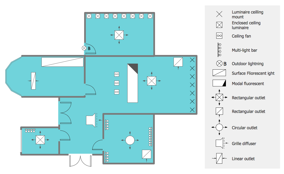
A Reflected Ceiling Plan (RCP) is a drawing of a room or building, looking down at the interior ceiling. Making RCP involves many different reflected ceiling plan symbols that can be managed using ConceptDraw PRO. Using ConceptDraw PRO you can design the reflected ceiling floor plan that shows the location of light fixtures and any other items that may be suspended from the ceiling. You can share your ceiling design ideas by saving drawings as graphics files, or printing them.- Design Legend In Building Plan
- How To use House Electrical Plan Software | How To Draw Building ...
- How To use House Electrical Plan Software | Home Electrical Plan ...
- Floor Plan Sample Office Legend
- Office Plan Legend Symbols
- How To Create Emergency Plans and Fire Evacuation | How to ...
- Mechanical Engineering | Home Electrical Plan | Mechanical ...
- Electrical Wiring Floor Plan Legend
- How To Draw Building Plans | How To Create Restaurant Floor Plan ...
- How To use House Electrical Plan Software | Electrical Drawing ...
- How to Create a Reflected Ceiling Floor Plan | Home Electrical Plan ...
- Plumbing and Piping Plans | Security and Access Plans | Flowcharts ...
- Security and Access Plans | How To Draw Building Plans | Plumbing ...
- Plumbing and Piping Plans | Home Electrical Plan | How To use ...
- How To use House Electrical Plan Software | How To Create ...
- Gantt Chart Legend
- Floor Plan Plumbing Layout With Legend
- How To Draw Building Plans | Plumbing and Piping Plans | Fire and ...
- Physical Security Plan | How To use House Electrical Plan Software ...
- Network Layout Floor Plans | Plumbing and Piping Plans | Security ...


