This site uses cookies. By continuing to browse the ConceptDraw site you are agreeing to our Use of Site Cookies.

Entity Relationship Diagram Symbols

Creating an entity-relationship (ER) model is to visually represent the structure of a business database, where data equates to entities (or objects) that are linked by defined relationships expressing dependencies and requirements. By nature it is an abstract visualization, the first step in the design process towards creating a logical and functional database.
ERD symbols used for professional ERD drawing are collected in libraries from the Entity-Relationship Diagram (ERD) solution for ConceptDraw PRO.

ERD Symbols and Meanings

Crow's foot notation is used in Barker's Notation, Structured Systems Analysis and Design Method (SSADM) and information engineering. Crow's foot diagrams represent entities as boxes, and relationships as lines between the boxes. Different shapes at the ends of these lines represent the cardinality of the relationship.
The Chen's ERD notation is still used and is considered to present a more detailed way of representing entities and relationships.
To create an ERD, software engineers mainly turn to dedicated drawing software, which contain the full notation resources for their specific database design - ERD symbols and meanings. CS Odessa has released an all-inclusive Entity-Relationship Diagram (ERD) solution for their powerful drawing program, ConceptDraw PRO.
How to Build an Entity Relationship Diagram (ERD)
HelpDesk

How to Set Line Jumps for Smart Connectors in ConceptDraw PRO

Connecting objects in ConceptDraw PRO is an easy task. You can use Chain, or Tree connection mode for automatic connection of multiple objects. Besides the automatic connection modes, ConceptDraw PRO offers few options to connect objects manually: Direct, Arc, Bezier, Smart, Curve and Round Connectors. You can make them square, arched or angled and also set vertical or horizontal orientation Thus, you can control how the jumps and orientation occurs on smart connectors. When two smart connectors cross each other you can control how the two intersecting lines look.

Basic Flowchart Symbols and Meaning

Flowchart Symbols and Meaning - Provides a visual representation of basic flowchart symbols and their proposed use in professional workflow diagram, standard process flow diagram and communicating the structure of a well-developed web site, as well as their correlation in developing on-line instructional projects. See flowchart's symbols by specifics of process flow diagram symbols and workflow diagram symbols.
How to Build a Flowchart

UML Activity Diagram. Design Elements

UML Activity Diagram illustrate the business and operational step-by-step workflow of components in a system and shows the overall flow of control.

Ice Hockey Rink Dimensions

Meeting ice hockey rules one should learn ice hockey rink terms, lines, zones etc. ConceptDraw PRO is an advanced drawing software that allows you produce ice hockey rink depiction of any complexity, from simple sketch drawing to detailed one as on example below.
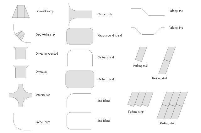
The vector stencils library Parking and roads contains 18 symbols of parking lots and strips, parking spaces, driveways, street junctions, and interchanges for parking facilities, on-street and off-street parking, and traffic management.
"A parking space is a location that is designated for parking, either paved or unpaved.
Parking spaces can be in a parking garage, in a parking lot or on a city street. It is usually designated by a white-paint-on-tar rectangle indicated by three lines at the top, left and right of the designated area. The automobile fits inside the space, either by parallel parking, perpendicular parking or angled parking." [Parking space. Wikipedia]
Use the design elements library Parking and roads to draw residential and commercial landscape design, parks planning, yard layouts, plat maps, outdoor recreational facilities, and irrigation systems using the ConceptDraw PRO diagramming and vector drawing software.
The shapes library Parking and roads is contained in the Site Plans solution from the Building Plans area of ConceptDraw Solution Park.
 , wrap-around island, sidewalk ramp, parking strip, parking stall, parking line, intersection, end island, driveway rounded, driveway, curb with ramp, corner curb, center island,

Cross Functional Flowchart

ConceptDraw PRO extended with Cross-Functional Flowcharts Solution from the Business Processes Area is the best software for quick and easy designing Cross Functional Flowchart of any complexity. Make sure in it right now!
HelpDesk

How to Connect Objects on PC

ConceptDraw PRO provides a few options for drawing connections between objects: Direct Connectors,
Smart, Arc, Bezier, Curve and Round Connectors. You can connect objects in your ConceptDraw diagram with proper connectors using the embedded automatic connection modes. This article describes how you can connect objects with connectors and how you can ascribe different types and behaviors.
Arrow 10 Technology
Arrow 10 Technology

Colored Baseball Field Diagram

ConceptDraw PRO software extended with the Baseball solution delivers libraries, templates and samples allowing baseball fans or specialists to draw baseball-related schemas in minutes. A complete set of predesigned fields and positions make drawing schemas as quickly as possible.