This rack diagram example was redesigned from the Wikimedia Commons file: Rackunit.svg. [commons.wikimedia.org/ wiki/ File:Rackunit.svg]
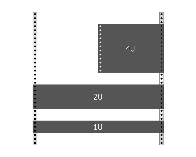
Rack with sample component sizes including an A/ V half-rack unit.
"A rack unit, U or RU as a unit of measure describes the height of equipment[which?] designed to mount in a 19-inch rack or a 23-inch rack. The 19-inch (482.6 mm) or 23-inch (584.2 mm) dimension reflects the width of the equipment mounting-frame in the rack including the frame; the width of the equipment that can be mounted inside the rack is less. One rack unit is 1.75 inches (4.445 cm) high. (This equates to one vershok, an obsolete unit of measurement used officially in Russia until 1924.)
The size of a piece of rack-mounted equipment is frequently described as a number in "U". For example, one rack unit is often referred to as "1U", 2 rack units as "2U" and so on." [Rack unit. Wikipedia]
The example "Rack with sample component sizes including an A/ V half-rack unit" was created using the ConceptDraw PRO diagramming and vector drawing software extended with the Rack Diagrams solution from the Computer and Networks area of ConceptDraw Solution Park.
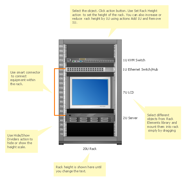
Rack with sample component sizes
Server rack diagrams visualize the the rack mounting of computer and network equipment as the drawing of frontal view of the rack with equipment installed. They are used for choosing the equipment or racks to buy, and help to organize equipment on the racks virtually, without the real installation.
"A 19-inch rack is a standardized frame or enclosure for mounting multiple equipment modules. Each module has a front panel that is 19 inches (482.6 mm) wide, including edges or ears that protrude on each side which allow the module to be fastened to the rack frame with screws." [19-inch rack. Wikipedia]
"A rack unit, U or RU is a unit of measure that describes the height of equipment designed to mount in a 19-inch rack or a 23-inch rack. The 19-inch (482.6 mm) or 23-inch (584.2 mm) dimension refers to the width of the equipment mounting frame in the rack including the frame; the width of the equipment that can be mounted inside the rack is less. One rack unit is 1.75 inches (4.445 cm) high.
The size of a piece of rack-mounted equipment is frequently described as a number in "U". For example, one rack unit is often referred to as "1U", 2 rack units as "2U" and so on.
A typical full size rack is 42U, which means it holds just over 6 feet of equipment, and a typical "half-height" rack would be 18-22U, or around 3 feet high." [Rack unit. Wikipedia]
The rack diagram template is included in the Rack Diagrams solution from the Computer and Networks area of ConceptDraw Solution Park.
Rack diagram template
 Baseball
The Baseball Solution extends ConceptDraw DIAGRAM.5 (or later) software with samples, templates, and libraries of vector objects for drawing baseball diagrams, plays, and illustrations. It can be used to make professional looking documents, presentations,
 Computer Network Diagrams
Computer Network Diagrams solution extends ConceptDraw DIAGRAM software with samples, templates and libraries of vector icons and objects of computer network devices and network components to help you create professional-looking Computer Network Diagrams, to plan simple home networks and complex computer network configurations for large buildings, to represent their schemes in a comprehensible graphical view, to document computer networks configurations, to depict the interactions between network's components, the used protocols and topologies, to represent physical and logical network structures, to compare visually different topologies and to depict their combinations, to represent in details the network structure with help of schemes, to study and analyze the network configurations, to communicate effectively to engineers, stakeholders and end-users, to track network working and troubleshoot, if necessary.
How To use House Electrical Plan Software


How To Draw Building Plans

Interior Design. Piping Plan — Design Elements

Chemical Engineering

 Cross-Functional Flowcharts
Cross-functional flowcharts are powerful and useful tool for visualizing and analyzing complex business processes which requires involvement of multiple people, teams or even departments. They let clearly represent a sequence of the process steps, the order of operations, relationships between processes and responsible functional units (such as departments or positions).
 Floor Plans
Construction, repair and remodeling of the home, flat, office, or any other building or premise begins with the development of detailed building plan and floor plans. Correct and quick visualization of the building ideas is important for further construction of any building.
- Rack units | Rack Diagrams | Design elements - Rack diagram ...
- Rack units | Design elements - Rack diagram | Rack diagram ...
- 1u Rack Panel Dimensions
- Rack units | Rack diagrams - Vector stencils library | Network ...
- Rack diagrams - Vector stencils library | Rack units | 1u Server Svg
- Rack diagrams - Vector stencils library | Rack diagram - Template ...
- What Is The Industry Standard For Rack Height In Rack Units
- Rack Diagrams | Rack Diagrams | Design Element: Rack Diagram ...
- Rack Diagrams | How to Create a Rack Diagram in ConceptDraw ...