Electrical Symbols — Rotating Equipment

Electrical Symbols, Electrical Diagram Symbols

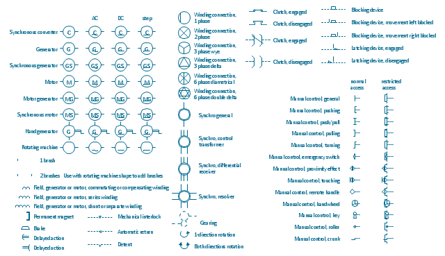
The vector stencils lybrary "Rotating equipment" contains 55 symbols of rotating equipment: converters, generators, motors, rotating machines, and their parts and labels.
Use to design systems containing rotating electrical equipment (i.e., motors), armatures, brushes, and related mechanical devices ( brakes, gearing, clutches, interlocks).
"The academic study of electric machines is the universal study of electric motors and electric generators. By the classic definition, electric machine is synonymous with electric motor or electric generator, all of which are electromechanical energy converters: converting electricity to mechanical power (i.e., electric motor) or mechanical power to electricity (i.e., electric generator). The movement involved in the mechanical power can be rotating or linear.
Although transformers do not contain any moving parts they are also included in the family of electric machines because they utilise electromagnetic phenomena.
Electric machines (i.e., electric motors) consume approximately 60% of all electricity produced. Electric machines (i.e., electric generators) produce virtually all electricity consumed. Electric machines have become so ubiquitous that they are virtually overlooked as an integral component of the entire electricity infrastructure. Developing ever more efficient electric machine technology and influencing their use are crucial to any global conservation, green energy, or alternative energy strategy." [Electric machine. Wikipedia]
The shapes example "Design elements - Rotating equipment" was drawn using the ConceptDraw PRO diagramming and vector drawing software extended with the Electrical Engineering solution from the Engineering area of ConceptDraw Solution Park.
Rotating equipment symbols
Electrical Symbols — Transformers and Windings
Electrical Symbols — Qualifying

Electrical Symbols — Semiconductor

Electrical Drawing Software and Electrical Symbols

Electrical Symbols — Composite Assemblies

Electrical Symbols — Semiconductor Diodes

The vector stencils library "Hydraulic pumps and motors" contains 74 symbols of hydraulic pump vector stencils, hydraulic motor symbols for engineering drawings of fluid power and hydraulic control systems.
"Hydraulic pumps are used in hydraulic drive systems and can be hydrostatic or hydrodynamic.
Hydrostatic pumps are positive displacement pumps while hydrodynamic pumps can be fixed displacement pumps, in which the displacement (flow through the pump per rotation of the pump) cannot be adjusted, or variable displacement pumps, which have a more complicated construction that allows the displacement to be adjusted." [Hydraulic pump. Wikipedia]
"A hydraulic motor is a mechanical actuator that converts hydraulic pressure and flow into torque and angular displacement (rotation). The hydraulic motor is the rotary counterpart of the hydraulic cylinder.
Conceptually, a hydraulic motor should be interchangeable with a hydraulic pump because it performs the opposite function - much as the conceptual DC electric motor is interchangeable with a DC electrical generator. However, most hydraulic pumps cannot be used as hydraulic motors because they cannot be backdriven. Also, a hydraulic motor is usually designed for the working pressure at both sides of the motor.
Hydraulic pumps, motors, and cylinders can be combined into hydraulic drive systems. One or more hydraulic pumps, coupled to one or more hydraulic motors, constitutes a hydraulic transmission." [Hydraulic motor. Wikipedia]
The shapes example "Design elements - Hydraulic pumps and motors" was created using the ConceptDraw PRO diagramming and vector drawing software extended with the Mechanical Engineering solution from the Engineering area of ConceptDraw Solution Park.
Hydraulic pump and motor symbols

- Motor Generator Symbol
- Mechanical Symbol Of Generator
- Electrical Symbol For Motor Coupled To Generator
- Is Symbol Of Synchronous Motor
- Hydraulic pumps and motors - Vector stencils library | Design ...
- Design elements - Hydraulic pumps and motors | Electrical Symbols ...
- Motor Winding Symbol
- Electrical Symbols — Rotating Equipment | UML Sequence Diagram ...
- Electrical Symbols — Rotating Equipment | Rotating equipment ...
- Symbol Of Winding