Process Flowchart


Home area networks (HAN). Computer and Network Examples
")

Local area network (LAN). Computer and Network Examples
. Computer and Network Examples")
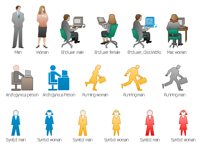
The vector stencils library "Cisco people" contains 17 pictogram symbols and clipart icons of people for drawing Cisco computer network diagrams.
The symbols example "Cisco people - Vector stencils library" was created using the ConceptDraw PRO diagramming and vector drawing software extended with the Cisco Network Diagrams solution from the Computer and Networks area of ConceptDraw Solution Park.
www.conceptdraw.com/ solution-park/ computer-networks-cisco
Man

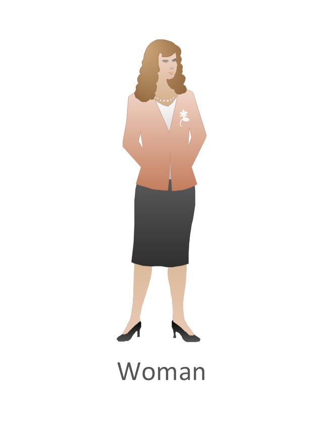
Woman
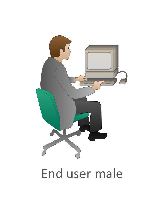
End user male
End user, CiscoWorks

Mac woman

End user female

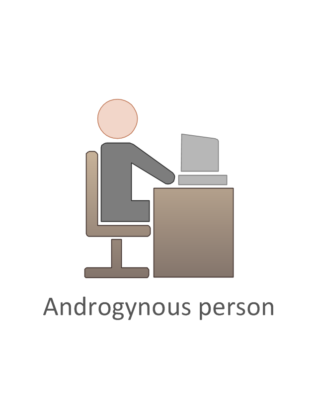
Androgynous person
Running woman

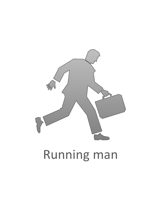
Running man

Running man, subdued
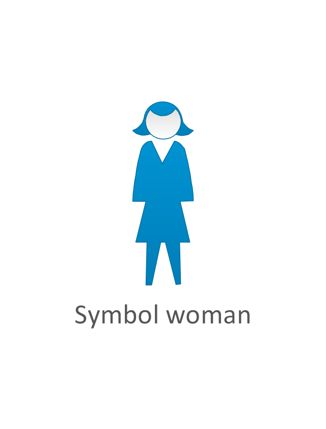
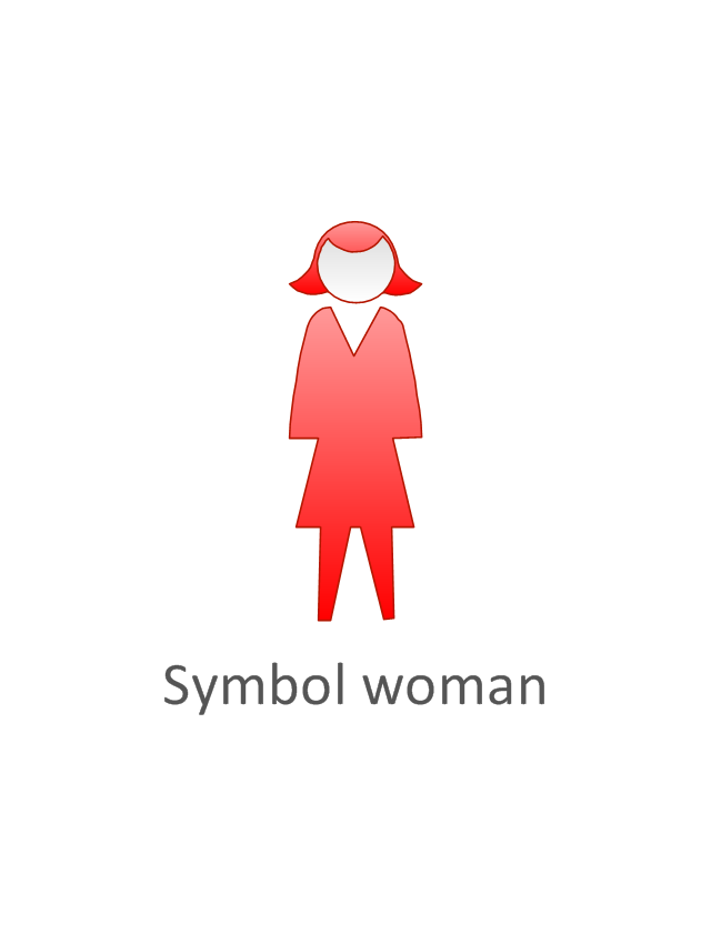
Symbol woman
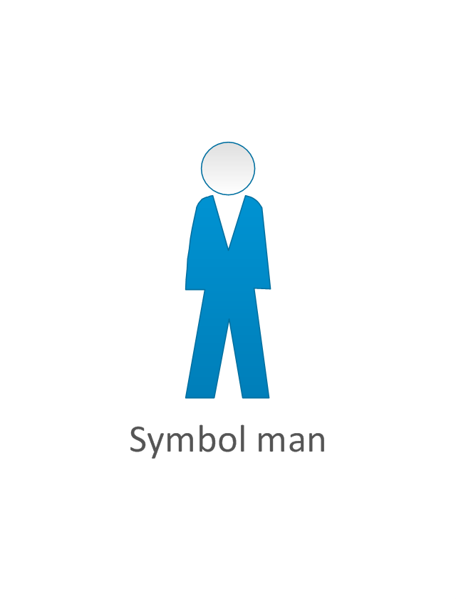
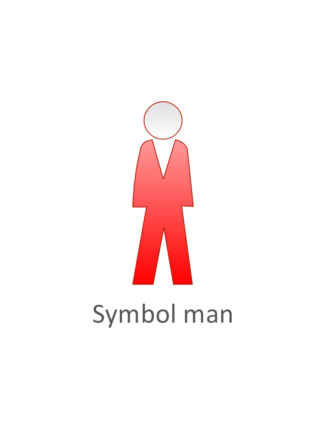
Symbol man
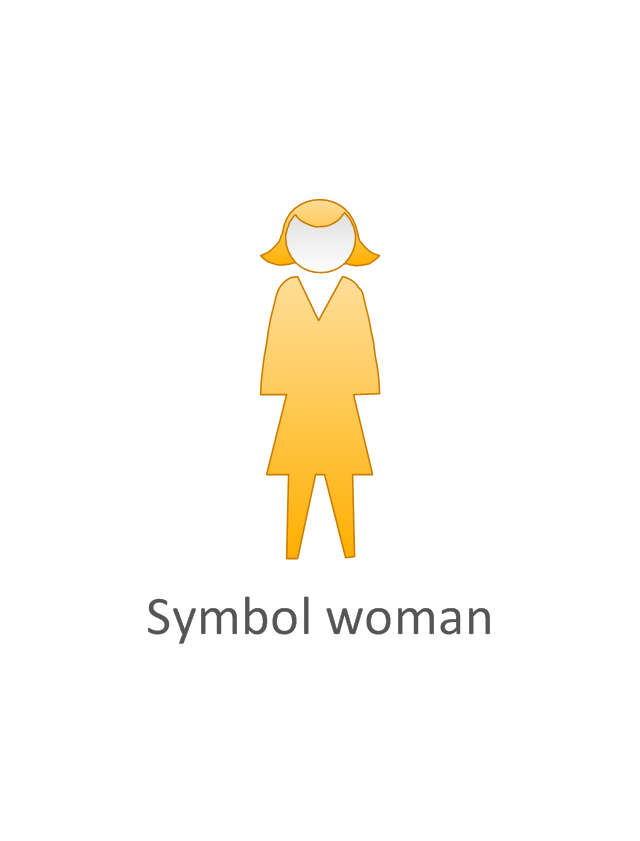
Symbol woman, yellow
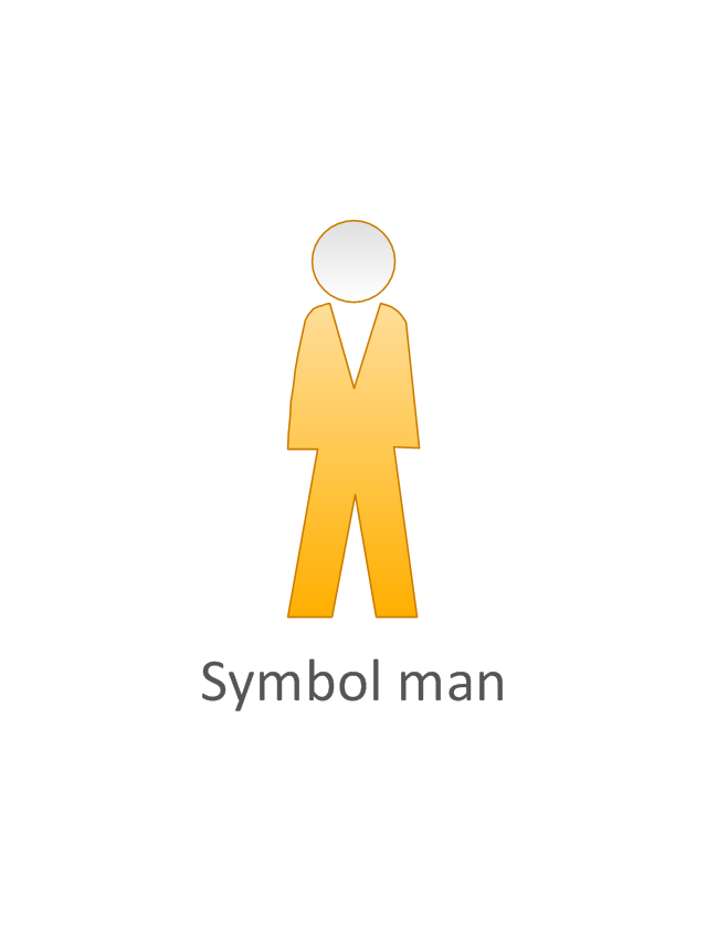
Symbol man, yellow
Symbol woman, red
Symbol man, red
Androgynous person, blue

Cisco People. Cisco icons, shapes, stencils and symbols
")
ERD Symbols and Meanings


The vector stencils library "Cisco people" contains 17 pictogram symbols and clipart icons of people: Man, Woman, End user male and female, End user Cisco works, Mac woman, Androgynous person, Running woman and man, Symbols men and women.
Create the computer network diagrams using the ConceptDraw PRO diagramming and vector drawing software with the design elements library "Cisco people".
The example "Design elements - Cisco people" is included in the Cisco Network Diagrams solution from the Computer and Networks area of ConceptDraw Solution Park.
Cisco people symbols
The vector stencils library "Sales symbols" contains 55 sales pictograms.
Use these icon set to draw your sales flowcharts, workflow diagrams and process charts with the ConceptDraw PRO diagramming and vector drawing software.
The vector stencils library "Sales symbols" is included in the Sales Flowcharts solution from the Marketing area of ConceptDraw Solution Park.
Use these icon set to draw your sales flowcharts, workflow diagrams and process charts with the ConceptDraw PRO diagramming and vector drawing software.
The vector stencils library "Sales symbols" is included in the Sales Flowcharts solution from the Marketing area of ConceptDraw Solution Park.
Banknotes

Box

Businessman

Businesswoman

Cellphone caller, man

Cellphone caller, woman

Clerk, man

Clerk, woman

Client computer

Cloud

Coins

Computer monitor

Crate

Credit cards

Credit card American Express

Credit card China UnionPay

Credit card Discover

Credit card Master
Credit card Visa

Customer, man

Customer, woman

Data base

Disqualified

Document

Documents

Document folder

Email

Exporting

Man figure

Woman figure

Folder closed

Folder opened

Importing

International

Mail

Mobile

Notes

PayPal

Phone

Phone caller, man

Phone caller, woman

Presentation slide

Qualified

Server

Shopping bag, empty

Shopping bag, full

Shopping cart, empty

Shopping cart, full

Spreadsheet

Technician

Time

USB flash card

User

Web form

Web page

Cisco Network Design. Cisco icons, shapes, stencils, symbols and design elements
")
How To Create Restaurant Floor Plan in Minutes


The vector stencils library "Cisco people" contains 17 pictogram symbols and clipart icons of people for drawing Cisco computer network diagrams.
The symbols example "Cisco people - Vector stencils library" was created using the ConceptDraw PRO diagramming and vector drawing software extended with the Cisco Network Diagrams solution from the Computer and Networks area of ConceptDraw Solution Park.
www.conceptdraw.com/ solution-park/ computer-networks-cisco
The symbols example "Cisco people - Vector stencils library" was created using the ConceptDraw PRO diagramming and vector drawing software extended with the Cisco Network Diagrams solution from the Computer and Networks area of ConceptDraw Solution Park.
www.conceptdraw.com/ solution-park/ computer-networks-cisco
Man
Woman
End user male
End user, CiscoWorks
Mac woman
End user female
Androgynous person
Running woman
Running man
Running man, subdued
Symbol woman
Symbol man
Symbol woman, yellow
Symbol man, yellow
Symbol woman, red
Symbol man, red
Androgynous person, blue
The vector stencils library "Cisco people" contains 17 pictogram symbols and clipart icons of people: Man, Woman, End user male and female, End user Cisco works, Mac woman, Androgynous person, Running woman and man, Symbols men and women.
Create the computer network diagrams using the ConceptDraw PRO diagramming and vector drawing software with the design elements library "Cisco people".
The example "Design elements - Cisco people" is included in the Cisco Network Diagrams solution from the Computer and Networks area of ConceptDraw Solution Park.
Create the computer network diagrams using the ConceptDraw PRO diagramming and vector drawing software with the design elements library "Cisco people".
The example "Design elements - Cisco people" is included in the Cisco Network Diagrams solution from the Computer and Networks area of ConceptDraw Solution Park.
Cisco people symbols
The vector stencils library "UML use case diagrams" contains 25 symbols for the ConceptDraw PRO diagramming and vector drawing software.
"Use case diagrams are usually referred to as behavior diagrams used to describe a set of actions (use cases) that some system or systems (subject) should or can perform in collaboration with one or more external users of the system (actors). Each use case should provide some observable and valuable result to the actors or other stakeholders of the system. ...
Use case diagrams are in fact twofold - they are both behavior diagrams, because they describe behavior of the system, and they are also structure diagrams - as a special case of class diagrams where classifiers are restricted to be either actors or use cases related to each other with associations. ...
Use case is usually shown as an ellipse containing the name of the use case. ...
Name of the use case could also be placed below the ellipse. ...
If a subject (or system boundary) is displayed, the use case ellipse is visually located inside the system boundary rectangle. Note, that this does not necessarily mean that the subject classifier owns the contained use cases, but merely that the use case applies to that classifier. ...
A list of use case properties - operations and attributes - could be shown in a compartment within the use case oval below the use case name. ...
Use case with extension points may be listed in a compartment of the use case with the heading extension points. ...
A use case can also be shown using the standard rectangle notation for classifiers with an ellipse icon in the upper right-hand corner of the rectangle and with optional separate list compartments for its features. ...
Subject (sometimes called a system boundary) is presented by a rectangle with subject's name, associated keywords and stereotypes in the upper left corner. Use cases applicable to the subject are located inside the rectangle and actors - outside of the system boundary. ...
Standard UML notation for actor is "stick man" icon with the name of the actor above or below of the icon. Actor names should follow the capitalization and punctuation guidelines for classes. The names of abstract actors should be shown in italics. ...
Custom icons that convey the kind of actor may also be used to denote an actor, such as using a separate icon(s) for non-human actors. ...
An actor may also be shown as a class rectangle with the standard keyword «actor», having usual notation for class compartments ...
An actor can only have binary associations to use cases, components, and classes. ...
An association between an actor and a use case indicates that the actor and the use case somehow interact or communicate with each other.
Only binary associations are allowed between actors and use cases.
An actor could be associated to one or several use cases. ...
A use case may have one or several associated actors." [uml-diagrams.org/ use-case-diagrams.html]
The example "Design elements - UML use case diagrams" is included in the Rapid UML solution from the Software Development area of ConceptDraw Solution Park.
UML use case diagram symbols

Office - Design Elements

Cisco Network Topology. Cisco icons, shapes, stencils and symbols
")
- Sales symbols - Vector stencils library | Visa Icon Png
- Person Vector Png
- Exit Running Icon Png
- Men With Phone Vector Png Hd
- Man Icon Vector Png
- Man Women Png Icon
- People Symbols Png
- End User Icon Png
- Vacation Symbol Png
- Person Infographic Icon Png
- Sit People Icon Vector Png
- Symbol Email Transparent Png
- Professions - Vector stencils library | Png Icon Flight Attendant
- Playing People Pictogram Png
- Master Card Icon Png
- Sales Order Icon Png
- Running Man Png
- Man Using Phone Icon Png
- Professions - Vector stencils library | Sales symbols - Vector stencils ...
- Sales symbols - Vector stencils library | Marketing - Vector stencils ...