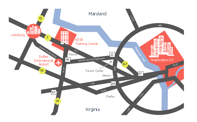
This location map sample was created on the base of the location map from the website of the NTSB Training Center.
"The NTSB Training Center is the training facility for the National Transportation Safety Board, an independent federal agency that investigates all civil aviation accidents in the United States and selected accidents in other modes of transportation.
The Training Center provides training for NTSB investigators and others from the transportation community to improve their practice of accident investigation techniques. The curriculum promotes independent, objective, and technically advanced accident investigations that will enhance the safety of all modes of transportation. ... Located on the Virginia campus of The George Washington University in Ashburn, the Training Center is ten miles from Washington Dulles Airport and 30 miles from Washington, D.C. Driving directions, maps, and a link to the virtual tour of our facility are available on the Campus page." [ntsb.gov/ trainingcenter/ about.htm]
The location map example "NTSB Training Center location" was created using the ConceptDraw PRO diagramming and vector drawing software extended with the Directional Maps solution from the Maps area of ConceptDraw Solution Park.
Location map
IDEF3 Standard

The vector stencils library "IDEF0 diagrams" contains 18 symbols for drawing IDEF0 function modeling diagrams using the ConceptDraw PRO diagramming and vector drawing software.
"The IDEF0 model ... is based on a simple syntax. Each activity is described by a verb-based label placed in a box. Inputs are shown as arrows entering the left side of the activity box while output are shown as exiting arrows on the right side of the box. Controls are displayed as arrows entering the top of the box and mechanisms are displayed as arrows entering from the bottom of the box. Inputs, Controls, Outputs, and Mechanisms are all referred to as concepts.
- Arrow : A directed line, composed of one or more arrow segments, that models an open channel or conduit conveying data or objects from source (no arrowhead) to use (with arrowhead). There are 4 arrow classes: Input Arrow, Output Arrow, Control Arrow, and Mechanism Arrow (includes Call Arrow). See Arrow Segment, Boundary Arrow, Internal Arrow.
- Box : A rectangle, containing a name and number, used to represent a function.
- Context : The immediate environment in which a function (or set of functions on a diagram) operates.
- Decomposition : The partitioning of a modeled function into its component functions.
- Fork : The junction at which an IDEF0 arrow segment (going from source to use) divides into two or more arrow segments. May denote unbundling of meaning.
- Function : An activity, process, or transformation (modeled by an IDEF0 box) identified by a verb or verb phrase that describes what must be accomplished.
- Join : The junction at which an IDEF0 arrow segment (going from source to use) merges with one or more other arrow segments to form a single arrow segment. May denote bundling of arrow segment meanings.
- Node : A box from which child boxes originate; a parent box. See Node Index, Node Tree, Node Number, Node Reference, Diagram Node Number." [IDEF0. Wikipedia]
The example "Design elements - IDEF0 diagram" is included in the IDEF0 Diagrams solution from the Software Development area of ConceptDraw Solution Park.
IDEF0 symbols

This example engineering drawing showing the hydraulic directional control valve usage with floating motor and pressure compensated pump is redesigned using the ConceptDraw PRO diagramming and vector drawing software from the Wikimedia Commons file: DCV 17.jpg.
[commons.wikimedia.org/ wiki/ File:DCV_ 17.jpg]
This file is licensed under the Creative Commons Attribution-Share Alike 3.0 Unported license.
[creativecommons.org/ licenses/ by-sa/ 3.0/ deed.en]
"Directional control valves are one of the most fundamental parts in hydraulic machinery as well and pneumatic machinery. They allow fluid flow into different paths from one or more sources. They usually consist of a spool inside a cylinder which is mechanically or electrically controlled. The movement of the spool restricts or permits the flow, thus it controls the fluid flow. ...
The spool (sliding type) consists of lands and grooves.The lands block oil flow through the valve body. The grooves allow oil or gas to flow around the spool and through the valve body. There are two fundamental positions of directional control valve namely normal position where valve returns on removal of actuating force and other is working position which is position of a valve when actuating force is applied. There is another class of valves with 3 or more position that can be spring centered with 2 working position and a normal position. ...
Directional control valves can be classified according to:
(1) number of ports;
(2) number of positions;
(3) actuating methods;
(4) type of spool." [Directional control valve. Wikipedia]
The fluid power equipment drawing example "Directional control valve" is included in the Mechanical Engineering solution from the Engineering area of ConceptDraw Solution Park.
www.conceptdraw.com/ solution-park/ engineering-mechanical
Hydraulic equipment schematic

"In electronics, a vacuum tube, electron tube (in North America), tube, or thermionic valve or valve (in British English) is a device controlling electric current through a vacuum in a sealed container. The simplest vacuum tube, the diode, contains only two elements; current can only flow in one direction through the device between the two electrodes, as electrons emitted by the hot cathode travel through the tube and are collected by the anode. Addition of a third and additional electrodes allows the current flowing between cathode and anode to be controlled in various ways. The device can be used as an electronic amplifier, a rectifier, an electronically controlled switch, an oscillator, and for other purposes.
Vacuum tubes mostly rely on thermionic emission of electrons from a hot filament or a cathode heated by the filament. Some electron tube devices rely on the properties of a discharge through an ionized gas." [Vacuum tube. Wikipedia]
"The EL34 is a thermionic valve or vacuum tube of the power pentode type. It has an international octal base (indicated by the '3' in the part number) and is found mainly in the final output stages of audio amplification circuits and was designed to be suitable as a series regulator by virtue of its high permissible voltage between heater and cathode and other parameters. The American RETMA tube designation number for this tube is 6CA7. Russian analog is 6P27S (Cyrillic: 6П27C )" [EL34. Wikipedia]
This circuit diagram sample was redrawn from the Wikipedia Commons file: EL34 schematics (circuit diagram).gif. [commons.wikimedia.org/ wiki/ File:EL34_ schematics_ %28circuit_ diagram%29.gif]
The example "Circuit diagram - EL 34 schematics" was drawn using the ConceptDraw PRO diagramming and vector drawing software extended with the Electrical Engineering solution from the Engineering area of ConceptDraw Solution Park.
www.conceptdraw.com/ solution-park/ engineering-electrical
EL34 shemathics

IDEF9 Standard

The logic gate diagram example "2-bit ALU" was redesigned from the Wikimedia Commons file: 2-bit ALU.svg.
[commons.wikimedia.org/ wiki/ File:2-bit_ ALU.svg]
This file is licensed under the Creative Commons Attribution-Share Alike 3.0 Unported license. [creativecommons.org/ licenses/ by-sa/ 3.0/ deed.en]
"In digital electronics, an arithmetic and logic unit (ALU) is a digital circuit that performs integer arithmetic and logical operations. The ALU is a fundamental building block of the central processing unit of a computer, and even the simplest microprocessors contain one for purposes such as maintaining timers. The processors found inside modern CPUs and graphics processing units (GPUs) accommodate very powerful and very complex ALUs; a single component may contain a number of ALUs. ...
Most of a processor's operations are performed by one or more ALUs. An ALU loads data from input registers. Then an external control unit tells the ALU what operation to perform on that data, and then the ALU stores its result into an output register. The control unit is responsible for moving the processed data between these registers, ALU and memory." [Arithmetic logic unit. Wikipedia]
The logic gate diagram example "2-bit ALU" was created using the ConceptDraw PRO diagramming and vector drawing software extended with the Electrical Engineering solution from the Engineering area of ConceptDraw Solution Park.
www.conceptdraw.com/ solution-park/ engineering-electrical
Logic gate diagram

- IDEF0 Diagram | Design elements - IDEF0 diagram | IDEF0 standard ...
- Design elements - IDEF0 diagram | Diagramming software for ...
- IDEF0 Diagram
- IDEF0 Diagram | Design elements - IDEF0 diagram | Software ...
- Design elements - IDEF0 diagram | IDEF0 Diagrams | ConceptDraw ...
- IDEF0 Diagram | Design elements - IDEF0 diagram | Basic ...
- IDEF0 standard with ConceptDraw PRO | IDEF0 Diagrams ...
- IDEF3 Standard | Circular arrows diagram - Business process life ...
- Design elements - IDEF0 diagram | ERD Symbols and Meanings ...
- How to Draw a Flowchart | Design elements - IDEF0 diagram ...
- Design elements - IDEF0 diagram | ERD Symbols and Meanings ...
- Circuit diagram - EL 34 schematics | Amplifier - Circuit diagram ...
- Interior Design Piping Plan - Design Elements | Pipes 2 - Vector ...
- Diagramming Software for Design UML Activity Diagrams | UML ...
- IDEF0 standard with ConceptDraw PRO | IDEF0 Diagram | IDEF0 ...
- Engineering | Electrical Diagram Software | Design elements ...
- AWS Simple Icons for Architecture Diagrams | Design elements ...
- Electrical Drawing Software | Flowchart Examples and Templates ...
- ERD Symbols and Meanings | Entity Relationship Diagram Symbols ...
- IDEF0 diagram template | IDEF0 Diagrams | Business Processes ...