 Interactive Voice Response Diagrams
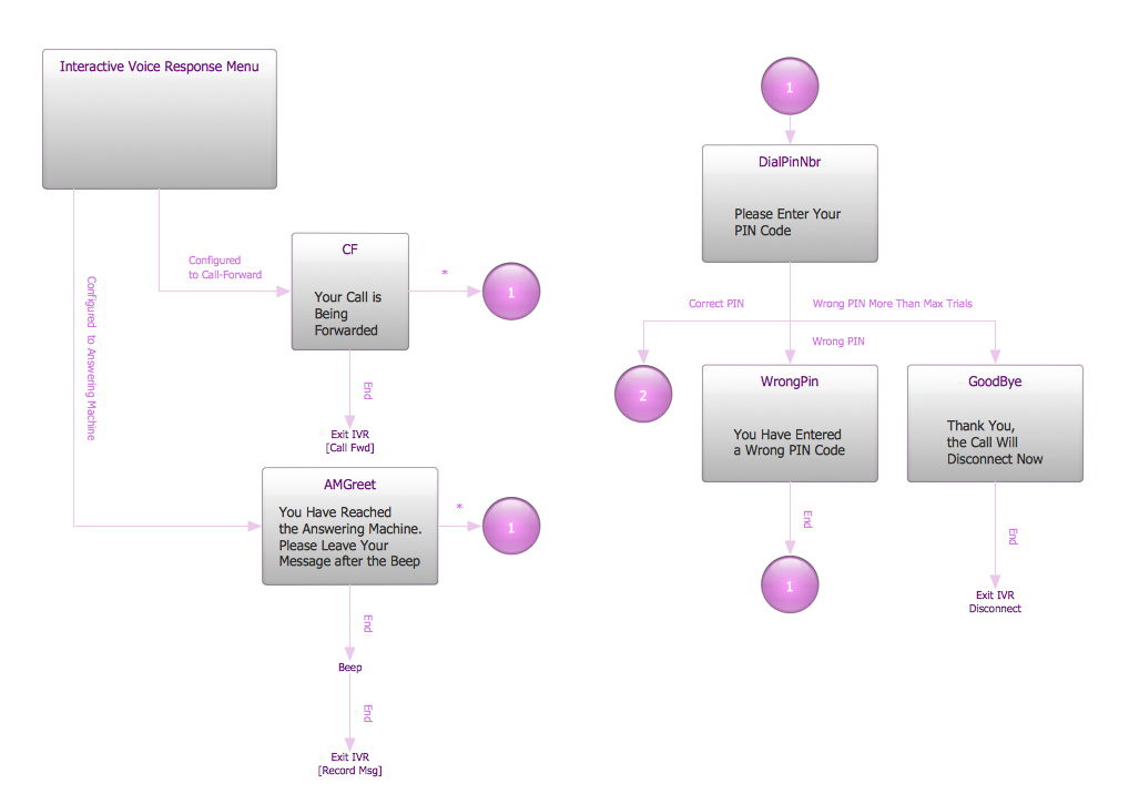
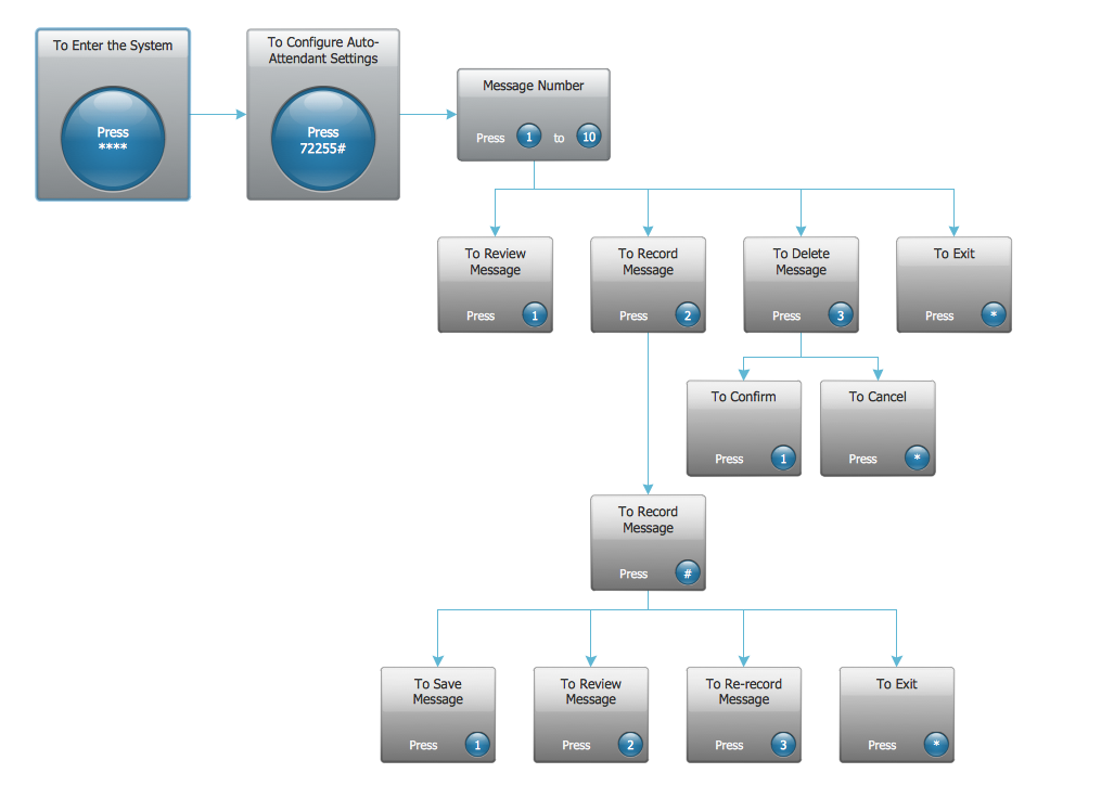
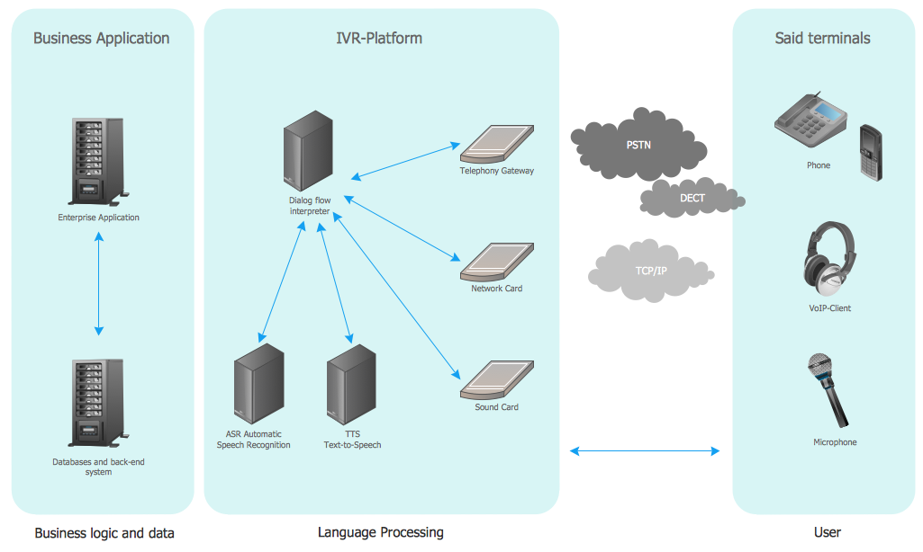
Interactive Voice Response Diagrams solution extends ConceptDraw DIAGRAM software with samples, templates and libraries of ready-to-use vector stencils that help create Interactive Voice Response (IVR) diagrams illustrating in details a work of interactive voice response system, the IVR system’s logical and physical structure, Voice-over-Internet Protocol (VoIP) diagrams, and Action VoIP diagrams with representing voice actions on them, to visualize how the computers interact with callers through voice recognition and dual-tone multi-frequency signaling (DTMF) keypad inputs.
What is IVR?
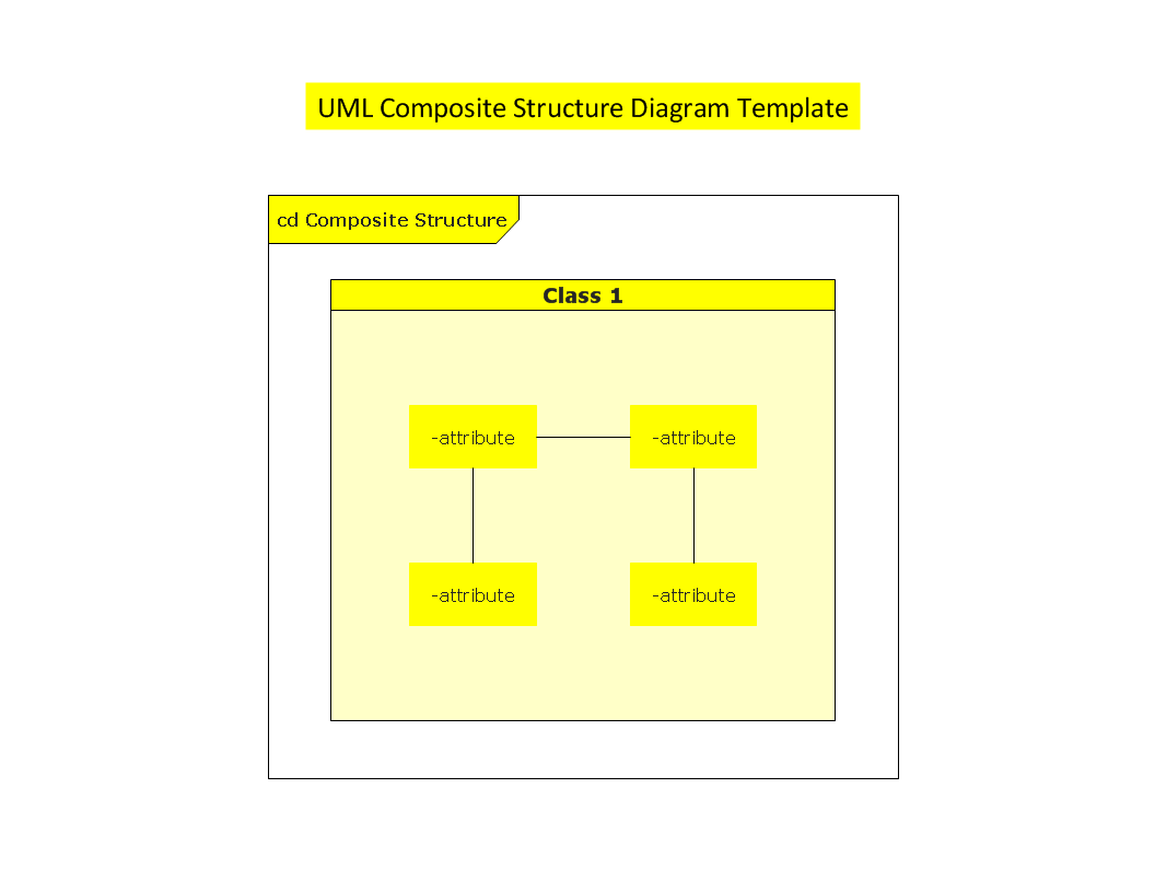
UML Composite Structure Diagram

HelpDesk
How to Create an Active Directory Diagram

Interactive Voice Response System
How To use Switches in Network Diagram


Hierarchical Network Topology
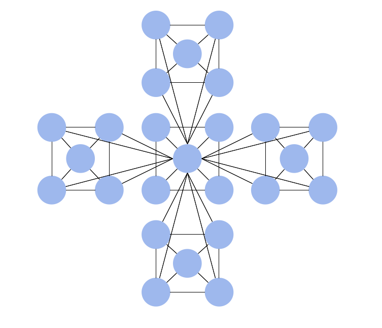
Interactive voice response (IVR) networks. Computer and Network Examples
HelpDesk
How to Create an Azure Architecture Diagram

Point to Point Network Topology

- Ivr Flow Chart Visio
- Ivr Flow Chart Template
- Root cause analysis tree diagram - Template | New Year card ...
- Fault Tree Analysis Diagrams | Network Diagram Examples ...
- Ivr Flow Chart Examples
- Ivr Tree Diagram
- Call center network diagram | IVR Network Diagram | Interactive ...
- Interactive Voice Response Diagrams | Fishbone Diagram | Fault ...
- Entity-Relationship Diagram (ERD) | Interactive Voice Response ...