Basic Flowchart Symbols and Meaning


Electrical Symbols — Inductors

Electrical Symbols, Electrical Diagram Symbols

Home Electrical Plan

How To use House Electrical Plan Software


Flowchart design. Flowchart symbols, shapes, stencils and icons


Audit Flowchart Symbols

"The symbols and conventions used in welding documentation are specified in national and international standards such as ISO 2553 Welded, brazed and soldered joints -- Symbolic representation on drawings and ISO 4063 Welding and allied processes -- Nomenclature of processes and reference numbers. The US standard symbols are outlined by the American National Standards Institute and the American Welding Society and are noted as "ANSI/ AWS".
In engineering drawings, each weld is conventionally identified by an arrow which points to the joint to be welded. The arrow is annotated with letters, numbers and symbols which indicate the exact specification of the weld. In complex applications, such as those involving alloys other than mild steel, more information may be called for than can comfortably be indicated using the symbols alone. Annotations are used in these cases." [Symbols and conventions used in welding documentation. Wikipedia]
The example chart "Elements of welding symbol" is redesigned using the ConceptDraw PRO diagramming and vector drawing software from the Wikipedia file: Elements of a welding symbol.PNG.
[en.wikipedia.org/ wiki/ File:Elements_ of_ a_ welding_ symbol.PNG]
The diagram example "Elements location of a welding symbol" is contained in the Mechanical Engineering solution from the Engineering area of ConceptDraw Solution Park.
Welding joint symbol chart

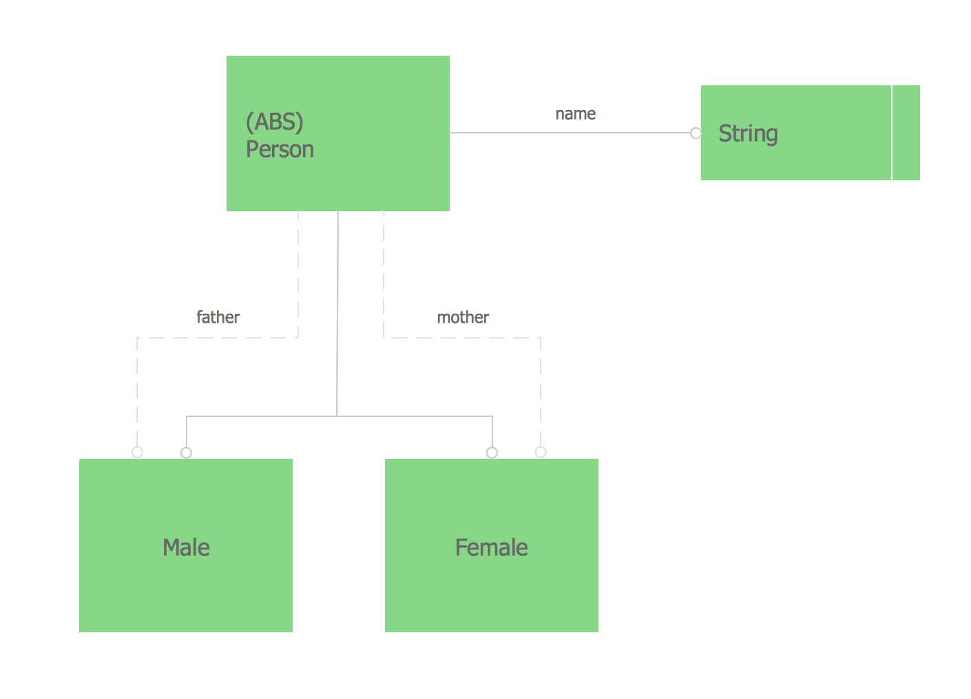
Express-G Diagram
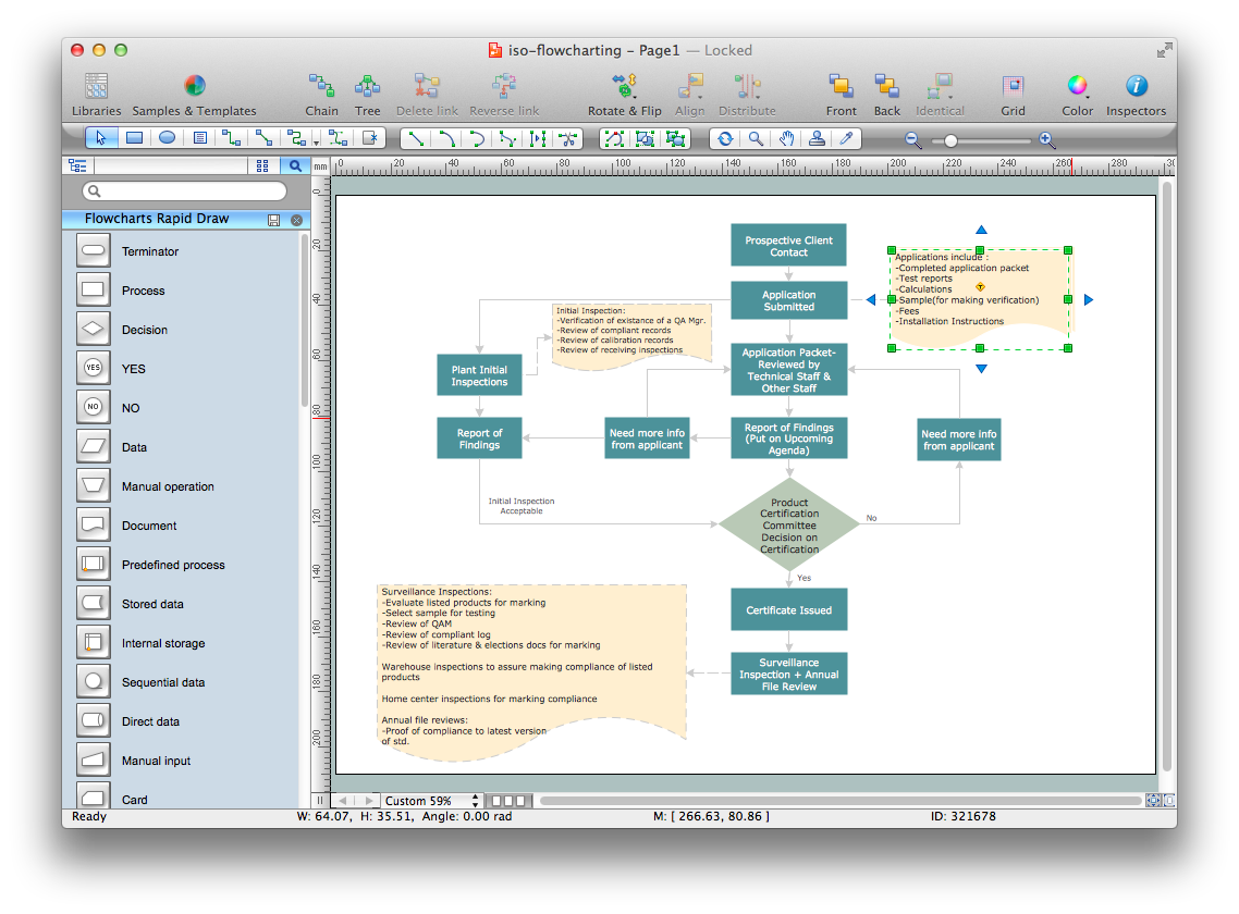
Quality Control Chart Software — ISO Flowcharting
- Plumbing and Piping Plans | Isometric Piping Drawing Symbols Pdf
- Basic Flowchart Symbols and Meaning | Iso Drafting Symbols
- Audit Flowcharts | Iso Engineering Symbols
- Iso Welding Symbols
- Total Quality Management with ConceptDraw | Iso Symbols Used In ...
- Iso Drawing Symbols Pdf Download
- Iso Welding Symbols On Drawings Pdf
- Isometric Piping Symbols Pdf
- Iso Aws Welding Symbols On Drawings