This site uses cookies. By continuing to browse the ConceptDraw site you are agreeing to our Use of Site Cookies.

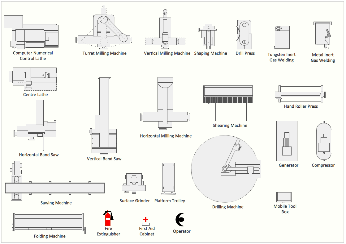
Mechanical Drawing Symbols

ConceptDraw DIAGRAM diagramming and vector drawing software extended with Mechanical Engineering solution from the Engineering area of ConceptDraw Solution Park provides a set of drawing tools and predesigned mechanical drawing symbols for fast and easy design various mechanical engineering diagrams, drawings and schematics.

Interior Design Machines and Equipment - Design Elements

Use Building Drawing Tools to develop the plant layouts for production,and receiving of manufactured goods.

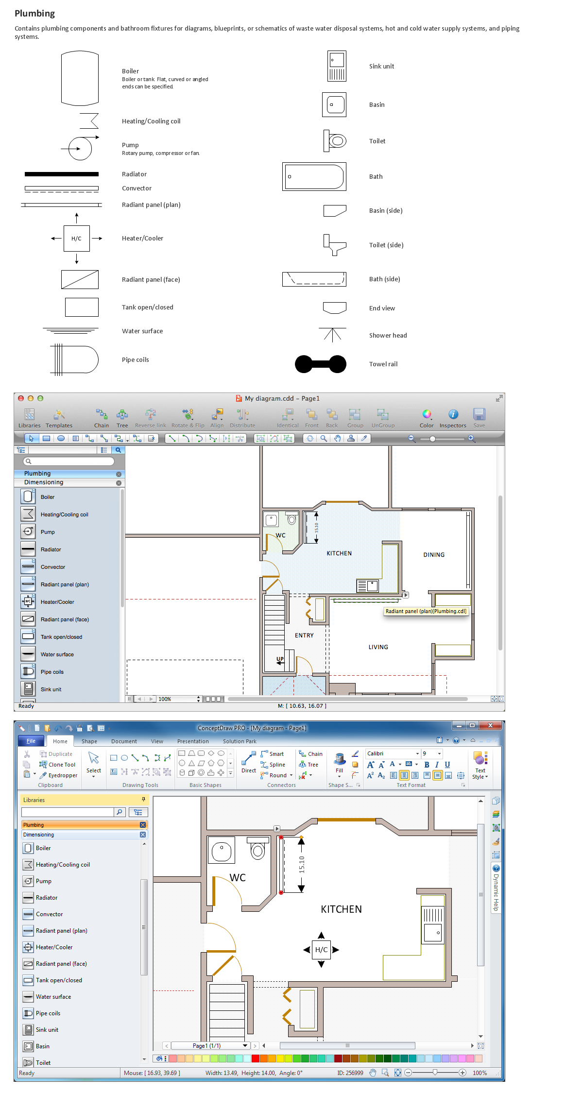
Building Drawing Software for Designing Plumbing

Use ConceptDraw to develop the annotated diagrams or schematics of plumbing systems and waste water engineering.
ConceptDraw has 1493 vector stencils in the 49 libraries that helps you to start using software for designing Building Drawing. You can use the appropriate stencils from Plumbing library with 21 objects.

Technical Drawing Software

Technical Drawing Software for drawing technical diagram, electrical and technical drawing. Download Drawing Software ConcepDraw for Free.
ConceptDraw DIAGRAM extended with: Mechanical Engineering Solution, Electrical Engineering Solution, Chemical and Process Engineering Solution from the Industrial Engineering Area is powerful software for business and technical drawing. Its powerful drawing tools, predesigned vector objects, templates, samples are helpful for creation all kinds of Technical Drawings and Technical Diagrams, Electrical and Mechanical Schematics, Circuit and Wiring Diagrams, Structural Drawings, and many other.

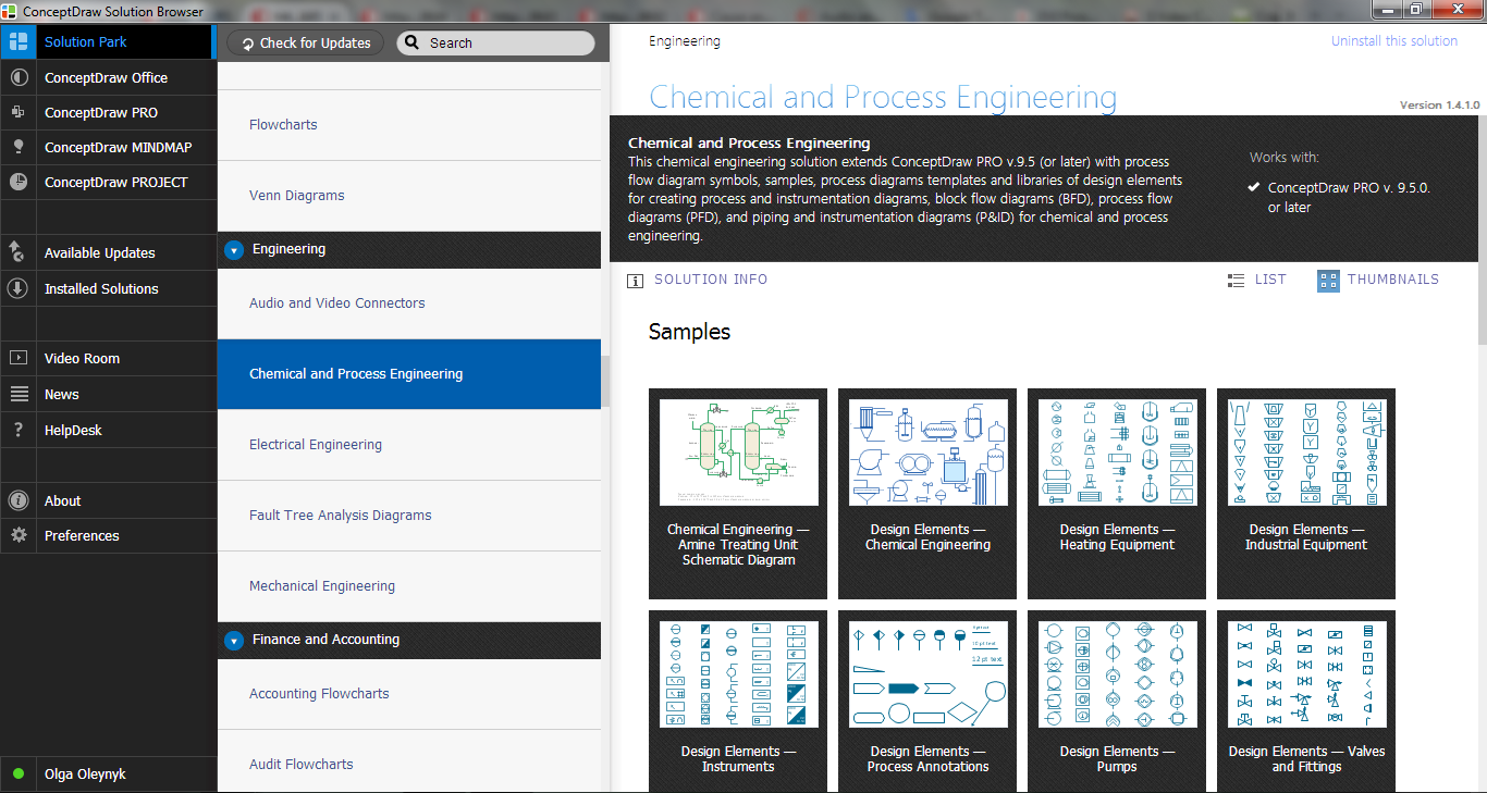
Piping and Instrumentation Diagram Software

ConceptDraw DIAGRAM is professional Piping and Instrumentation Diagram (P&ID) Software.
Plumbing and Piping Plans solution helps you create quick and easy: key piping and instrument details ,piping diagrams
instrumentation diagrams, schemes of hot and cold water supply systems, control and shutdown schemes, diagrams of plumbing systems, heating schemes, schematics of waste water disposal systems, safety and regulatory requirements, diagrams of ventilation systems, mechanical diagrams, industrial diagrams, basic start up and operational information.

Electrical Symbols — Rotating Equipment

Electrical rotating machines, such as motors and generators, are vital assets for any power plant or large industrial company.
An electric motor is an electrical machine that converts electrical energy into mechanical energy. The reverse of this would be the conversion of mechanical energy into electrical energy and is done by an electric generator.
In normal motoring mode, most electric motors operate through the interaction between an electric motor's magnetic field and winding currents to generate force within the motor. In certain applications, such as in the transportation industry with traction motors, electric motors can operate in both motoring and generating or braking modes to also produce electrical energy from mechanical energy.

26 libraries of the Electrical Engineering Solution of ConceptDraw DIAGRAM make your electrical diagramming simple, efficient, and effective. You can simply and quickly drop the ready-to-use objects from libraries into your document to create the electrical diagram.

Interior Design Piping Plan - Design Elements

Every apartment needs renovation from time to time, as some home systems such as wiring or plumbing may fall out. When developing the future design of a piping system, the engineer should take into account many aspects. Replacing the worn plumbing begins with the choice of materials and sizes of pipes for the new system. Each proposal has its own pros and cons that should be considered before purchasing. It is also relevant to draw attention to temperature changes that might effect pipes, such as freezing or thermal expansion. Let’s take a closer look at possible pipes materials.
Recently, steel pipes were the most common, and now they can still be purchased. The most important advantage of steel is that it is eco-friendly and the fact that they have passed the test of time and pipes of good quality can function for more than 50 years. Remaining pros: high operating pressure and temperature, as well as small thermal expansion. The negative sides of steel pipes include their big we

mechanical engineering, mechanical design software, mechanical drawing symbols, mechanical drawing software Mechanical Engineering

mechanical engineering, mechanical design software, mechanical drawing symbols, mechanical drawing software
This solution extends ConceptDraw DIAGRAM.9 mechanical drawing software (or later) with samples of mechanical drawing symbols, templates and libraries of design elements, for help when drafting mechanical engineering drawings, or parts, assembly, pneumatic,
"A hydraulic circuit is a system comprising an interconnected set of discrete components that transport liquid. The purpose of this system may be to control where fluid flows (as in a network of tubes of coolant in a thermodynamic system) or to control fluid pressure (as in hydraulic amplifiers).
... hydraulic circuit theory works best when the elements (passive component such as pipes or transmission lines or active components such as power packs or pumps) are discrete and linear. This usually means that hydraulic circuit analysis works best for long, thin tubes with discrete pumps, as found in chemical process flow systems or microscale devices." [Hydraulic circuit. Wikipedia]
The engineering drawing example "Hydraulic circuits" was redrawn using ConceptDraw PRO diagramming and vector drawing software from the Wikimedia Commons file: Hydraulic circuits.png.
[commons.wikimedia.org/ wiki/ File:Hydraulic_ circuits.png]
This file is licensed under the Creative Commons Attribution-Share Alike 3.0 Unported license.
[creativecommons.org/ licenses/ by-sa/ 3.0/ deed.en]
The engineering drawing example "Hydraulic circuits" is included in the Mechanical Engineering solution from the Engineering area of ConceptDraw Solution Park.
Hydraulic circuit schematic
Hydraulic circuit schematic, variable arrow, spring, variable spring, non-variable spring, shaft, rod, pump, hydraulic, oil tank, non-return, valve, junction, crossing, four-port, three-position, valve, fixed displacement hydraulic pump, fixed displacement hydraulic motor, dot, line, junction, callout, box, flow path, arrow, flow path, direction, rectilinear motion,

Process Flow Diagram Symbols

Chemical and Process Engineering Solution from the Industrial Engineering Area of ConceptDraw Solution Park is a unique tool which contains variety of predesigned process flow diagram symbols for easy creating various Chemical and Process Flow Diagrams in ConceptDraw DIAGRAM.