UML Class Diagram Generalization Example UML Diagrams

UML Sample Project

Booch OOD Diagram

UML Use Case Diagram Example. Registration System

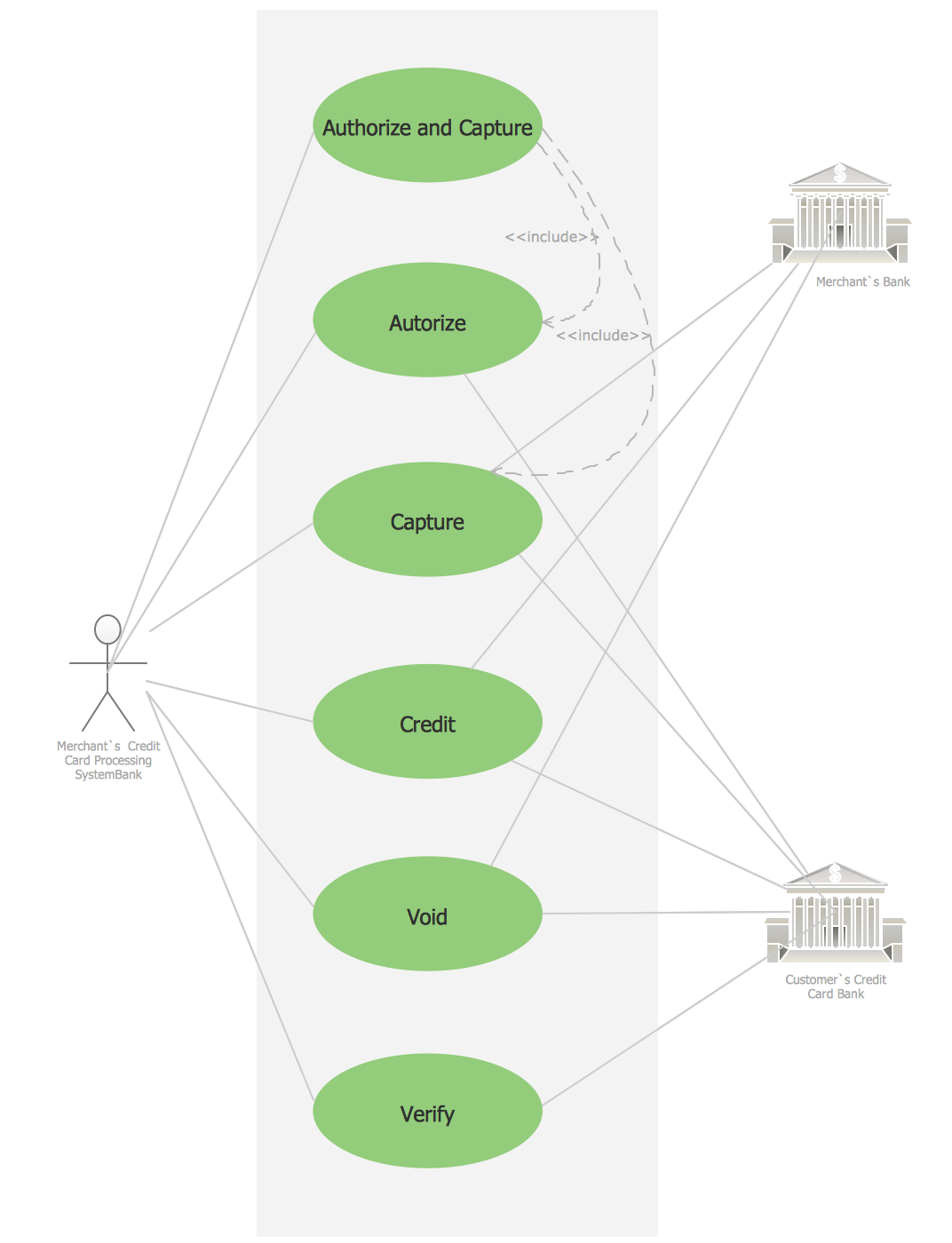
Credit Card Processing System UML Diagram
UML Diagram Types List

UML Class Diagram Example for GoodsTransportation System
 ATM UML Diagrams
The ATM UML Diagrams solution lets you create ATM solutions and UML examples. Use ConceptDraw DIAGRAM as a UML diagram creator to visualize a banking system.
UML Notation

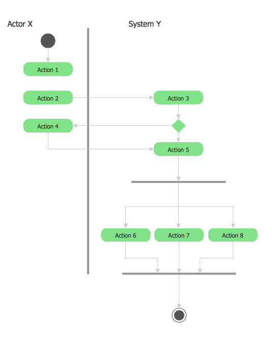
UML 2 4 Process Flow Diagram
- UML Flowchart Symbols | Activity Diagram Of Atm Management ...
- ATM UML Diagrams | Library Management System Project Report ...
- UML Diagram | UML Class Diagram Generalization Example UML ...
- Use Case Diagram For Library Management System Ppt Download
- IDEF1X Standard | UML Collaboration Diagram (UML2.0) | UML ...
- UML Package Diagram . Design Elements | UML Notation | AWS ...
- Use Case Diagrams technology with ConceptDraw PRO ...
- How to Manage Multiple Projects on Windows | Manage Social ...
- Class UML Diagram for Bank Account System | Bank UML Diagram ...