 Plant Layout Plans
This solution extends ConceptDraw PRO v.9.5 plant layout software (or later) with process plant layout and piping design samples, templates and libraries of vector stencils for drawing Plant Layout plans. Use it to develop plant layouts, power plant desig
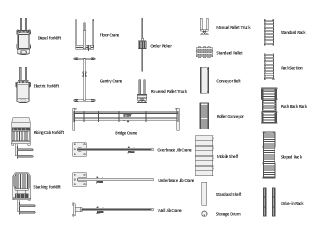
The vector stencils library "Storage and distribution" contains 24 symbols of storage and distribution industrial equipment.
Use the design elements library "Storage and distribution" to draw industrial warehouse plans and storage and distribution equipment layouts using the ConceptDraw PRO diagramming and vector drawing software.
"A warehouse is a commercial building for storage of goods. Warehouses are used by manufacturers, importers, exporters, wholesalers, transport businesses, customs, etc. They are usually large plain buildings in industrial areas of cities and towns and villages. They usually have loading docks to load and unload goods from trucks. Sometimes warehouses are designed for the loading and unloading of goods directly from railways, airports, or seaports. They often have cranes and forklifts for moving goods, which are usually placed on ISO standard pallets loaded into pallet racks.
Some of the most common warehouse storage systems are:
Pallet racking including selective, drive-in, drive-thru, double-deep, pushback, and gravity flow;
Mezzanine including structural, roll formed, racks;
Vertical Lift Modules;
Horizontal Carousels;
Vertical Carousels." [Warehouse. Wikipedia]
The shapes library "Storage and distribution" is included in the Plant Layout Plans solution from the Building Plans area of ConceptDraw Solution Park.
Storage and distribution symbols
HelpDesk
How to Create a Plant Layout Design

HelpDesk
How to Draw a Process Flow Diagram in ConceptDraw PRO

HelpDesk
How to Draw an Electrical Scheme Using ConceptDraw Solution Park

 Engineering
This solution extends ConceptDraw PRO v9.4 with the ability to visualize industrial systems in electronics, electrical, chemical, process, and mechanical engineering.
 Universal Diagramming Area
This area collects solutions for drawing diagrams, charts, graphs, matrices, geographic and road maps for education, science, engineering, business.
The vector stencils library "Valves" contains 91 symbols of piping and plumbing valves.
"A valve is a device that regulates, directs or controls the flow of a fluid (gases, liquids, fluidized solids, or slurries) by opening, closing, or partially obstructing various passageways. Valves are technically valves fittings, but are usually discussed as a separate category. In an open valve, fluid flows in a direction from higher pressure to lower pressure.
The simplest, and very ancient, valve is simply a freely hinged flap which drops to obstruct fluid (gas or liquid) flow in one direction, but is pushed open by flow in the opposite direction. This is called a check valve, as it prevents or "checks" the flow in one direction.
People in developed nations use valves in their daily lives, including plumbing valves, such as taps for tap water, gas control valves on cookers, small valves fitted to washing machines and dishwashers, safety devices fitted to hot water systems..." [Valve. Wikipedia]
Use the design elements library "Valves" to draw building plans, schematic diagrams, blueprints, or technical drawings of industrial piping systems; process, vacuum, and fluids piping; hydraulics piping; air and gas piping; materials distribution; and liquid transfer systems using the ConceptDraw PRO diagramming and vector drawing software.
The shapes library "Valves" is included in the Plumbing and Piping Plans solution from the Building Plans area of ConceptDraw Solution Park.
Valve symbols

 Manufacturing and Maintenance
Manufacturing and maintenance solution extends ConceptDraw PRO software with illustration samples, templates and vector stencils libraries with clip art of packaging systems, industrial vehicles, tools, resources and energy.
IDEF1 standard

- How To Draw Building Plans | How To Create Restaurant Floor ...
- Plant Layout Plans | Building Drawing Software for Design Storage ...
- Plant Layout Plans | Interior Design Storage and Distribution ...
- Plant Layout Plans | How To Draw Building Plans | Interior Design ...
- Building Drawing Software for Design Site Plan | How To Draw ...
- How To Draw Building Plans | How To use Building Plan Examples ...
- CAD Drawing Software for Making Mechanic Diagram and Electrical ...
- Factory layout floor plan | Design elements - Machines and ...
- Building Drawing Software for Design Storage and Distribution ...
- Building Drawing Software for Design Office Layout Plan
- How To use House Electrical Plan Software | Electrical Drawing ...
- Plant Layout Plans | Interior Design Storage and Distribution ...
- Security and Access Plans | How To Draw Building Plans | Sport ...
- Building Drawing Design Element: Plumbing | Interior Design ...
- Building Drawing Design Element: Storage and Distribution
- Warehouse layout floor plan | Design elements - Storage and ...
- Building Drawing Design Element: Storage and Distribution | Interior ...
- Building Drawing Design Element: Storage and Distribution
- Engineering | Design elements - Valves and fittings | Security system ...
- Design Element: Rack Diagram for Network Diagrams | Rack ...