Made with
ConceptDraw
DIAGRAM 18

IDEF1 standard

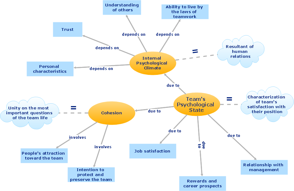
Industrial activity of the enterprise may be presented as the permanent process of change of objects which constitute this enterprise. These objects are workers, material resources, production, finances and many other things. This can be either physical or intellectual objects, for example ideas and technologies. To manage these objects the corresponding documentation is necessary. In this documentation there will be registered and represented the current state of the object, its preceding and even predictable states. Such documentation is called an information field of an enterprise, and the circulation of documents is called - information flows.

IDEF1 standard is elaborated for representation of information flows at the visual graphical view. With the help of diagrams created accordingly to this standard, it is possible to analyze and study information flows, their interaction and interrelation for discovering weak spots in the existing structure of the information field of an enterprise.Also IDEF1 diagrams include objects of the industrial activity of an enterprise which lets study and analyze the existing information about these objects.

The purpose of this analysis is the more qualitative management of information and information flows of an enterprise. Results of the analysis of IDEF1 diagrams can be used for planning of the enterprise activity and increasing of the effectiveness of the information management.

Using visual graphical objects IDEF1 standard allows to model information interrelations and differences between:

  • Real objects (workers, resources);
  • Physical and abstract dependencies, existing between real objects;
  • Information about real objects ( personal files of workers, reports, descriptions);
  • Structure of data, used for acquiring, accumulation, usage and management of information (statistic data base);

Accordingly to IDEF1 standard, elements of the information field as well as their properties and interrelations are divided into classes. There is also a concept of an entity in IDEF1 standard. The class of the entity is the totality of information about the definite object and the group of objects of the enterprise information field, which has the relation directly to the enterprise. The main characteristics of entities are originality, which allows to identify one entity from another, and stability, which implies permanent accumulation of information about the object.

In IDEF1 standard the entity has the name and attributes. Attributes are a set of characteristic properties of an object. The class of attributes of an entity is a set of names of attributes and values of these attributes corresponding to the given object or to the group of objects. Attributes by which the entity is unambiguously identified are called dominant.Every entity may have several dominant attributes.

According to IDEF1 standard all interrelations between entities form a class of interrelations. If dominant attributes of one entity come into class of attributes of another entity there is an interrelation between these entities. The name of interrelation is always expressed in the form of a verb (E.g. “work at”, “reckoned on”, “assigned to”, etc.).

As an example of interrelated entities there can be a product produced by the enterprise department.

Operating Systems:     Macintosh® (Mac OS X 10.7. or later)     Microsoft® Windows® 7/VISTA/XP
Price:   ConceptDraw DIAGRAM   $199
IDEF1 standard *
TEN RELATED HOW TO's:
IDEF →
IDEF Business Process Diagrams solution from the Business Processes area of ConceptDraw Solution Park extends ConceptDraw DIAGRAM vector graphics and diagramming software with the ability of fast and easy drawing various types of IDEF diagrams.IDEF *
Picture: IDEF
Related Solution:
The Entity-Relationship Diagram (ERD) solution from ConceptDraw Solution Park extends ConceptDraw DIAGRAM vector graphics and diagramming software with the ability to describe a database using the Entity-Relationship (Chen) model. Use it for design your ERDs and verify that ConceptDraw DIAGRAM offers the best ERD diagrams software tools for design element Chen notation.Entity Relationship Diagram - ERD - Software for Design  <br>Chen ER Diagrams *
Picture: Entity Relationship Diagram - ERD - Software for Design Chen ER Diagrams
Related Solution:
One of the key roles at the attracting visitors in catering establishments of different formats plays their visual solution, design of advertising elements of fast foods and restaurants. ConceptDraw DIAGRAM software enhanced with unique Food Court solution from the Food and Beverage area of ConceptDraw Solution Park allows to design inviting and attractive signboards, pictorial menus with appetizing food pictures.Food Pictures *
Picture: Food Pictures
Related Solution:
BPMN →
You need to draw professional looking BPMN diagrams quick and easy? Pay please your attention on ConceptDraw DIAGRAM diagramming and vector drawing software. Extended with Business Process Diagram Solution from the Business Processes Area it will be ideal for your.BPMN *
Picture: BPMN
Related Solution:
If you are just a beginner in drawing flowcharts, it may seem that a sheet of paper and a pen are just enough. However, at the time you would want to share your results, diagramming applications would suite you better. it’s very easy to create diagrams that way and to discover new kinds of flowcharts. The huge collection of sample ConceptDraw diagrams, charts, illustrations and other types of business drawings includes a wide range of business themes. A huge number of graphic images of ConceptDraw documents is divides on business application areas according to business-oriented solutions for which they were made.Here is a short visual list of samples of flowcharts, process diagrams, UML models, management charts, computer network diagrams, maps, infographics, illustrations, etc. In short, each ConceptDraw solution is accompanied with at least ten samples representing some particular examples of the application of the given chart.Applications *
Picture: Applications
When trying to figure out the nature of the problems occurring within a project, there are many ways to develop such understanding. One of the most common ways to document processes for further improvement is to draw a process flowchart, which depicts the activities of the process arranged in sequential order — this is business process management. ConceptDraw DIAGRAM is business process mapping software with impressive range of productivity features for business process management and classic project management. This business process management software is helpful for many purposes from different payment processes, or manufacturing processes to chemical processes. Business process mapping flowcharts helps clarify the actual workflow of different people engaged in the same process. This samples were made with ConceptDraw DIAGRAM — business process mapping software for flowcharting and used as classic visio alternative because its briefly named "visio for mac" and for windows, this sort of software named the business process management tools. This flowchart diagram shows a process flow of project management. The diagram that is presented here depicts the project life cycle that is basic for the most of project management methods. Breaking a project into phases allows to track it in the proper manner. Through separation on phases, the total workflow of a project is divided into some foreseeable components, thus making it easier to follow the project status. A project life cycle commonly includes: initiation, definition, design, development and implementation phases. Distinguished method to show parallel and interdependent processes, as well as project life cycle relationships. A flowchart diagram is often used as visual guide to project. For instance, it used by marketing project management software for visualizing stages of marketing activities or as project management workflow tools. Created with ConceptDraw DIAGRAM — business process mapping software which is flowcharting visio alternative or shortly its visio for mac, this sort of software platform often named the business process management tools.Process Flowchart
Picture: Process Flowchart: A Step-by-Step Comprehensive Guide
Related Solution:
The vector stencils library Yourdon and Coad Notation from the solution OOAD contains specific symbols of the Yourdon and Coad notation such as data store symbol, data process symbol, loop symbol for ConceptDraw DIAGRAM software.Yourdon and Coad Diagram
Picture: Yourdon and Coad Diagram
ConceptDraw DIAGRAM application is perfect for creating workflow diagrams. This application contains specific features and technologies designed to draw diagrams faster, such as RapidDraw and Arrows10. ConceptDraw DIAGRAM software extended with the Workflow Diagrams solution gives you a flexible tool to draw any kind of workflow.Workflow Application *
Picture: Workflow Application
Related Solution:
A flowchart maker is a software showing the interaction, sequence or organization. It also known as flowchart maker or ConceptDraw DIAGRAM standard supplied with different types of symbol collections: standard symbols, branded set and authored. It used strictly for enhancing scientific or business documents with abstract explanatory pictures. Business graphic applications show a special knowledge representations and include many features for creating schematic pictures. These graphic tools are known as flowchart maker or flowchart maker software.Flowchart Maker *
Picture: Flowchart Maker
Related Solution:
There are many ways to define the flow of information within a system. Structured-systems analysis method often uses data flow diagrams to show data flow, data storages and data processing visualization. These diagrams are easy to develop and quite useful. Here is a dataflow diagram presenting an example of the manufacturing process flow. The oval process shapes represent a process that controls data within the current system. The process may produce data or make some action based on data. Data flows are represented by lines. They show the movement of information through the system. The direction of the data flow is depicted by the arrow. The external entities are shown by rectangles. They represent the external entities interacting with the system. The data store objects (unclosed rectangles) are used to show data bases participating in a process flow.Data Flow Diagram *
Picture: Data Flow Diagram
Related Solution:
ConceptDraw
DIAGRAM 18